
|
Cathodic Protection Training Course
Cathodic Protection Training Course
|
|
Module 01 page 5 THE BASIC CONCEPT OF PIPELINE CATHODIC PROTECTION
As stated before, everything has a 'potential', which has an effect on it's relationship with it's environment. Corrosion is effected by this relationship, as it is an electro-chemical reaction.
The basic concept of cathodic protection is that the electrical potential of the subject metal is reduced below its corrosion potential, and that it will then be incapable of going into solution, or corroding. The reasons for this are given in thermo-dynamic theory but these will not be discussed at this stage.
The corrosion reaction and cathodic protection mechanism has been defined by many scientists and has become established beyond dispute. Many books and papers have been published, giving details of the scientific background of corrosion and corrosion control, as a result of many years of research by respected and sincere specialists. It is not intended to dispute any of this work or the conclusions drawn.
Battery technology can be compared to corrosion control Technology
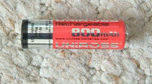
The principles of corrosion reactions are used in the design and construction of expendable and re-chargeable batteries and accumulators, which play such a major part in modern life. A battery is designed to allow a chemical reaction to cause an electrical current to pass through a desired path, giving energy to the appliance. The battery has a very carefully composed electrolyte which has qualities to ensure a predictable reaction with the other components of the battery.
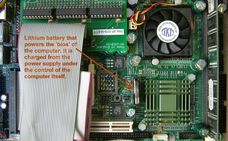
Corrosion within a battery can be controlled by external electrical techniques which are in common use. Some batteries have a reversible reaction which enables them to be recharged by adjusting the electrical 'pressure' at the terminals. Many appliances are nowadays controlled by computers to balance the reaction equilibrium to suit their own power demands.
All this is possible because the battery is a manufactured unit, designed for the purpose of receiving and supplying electrical current.
CATHODIC PROTECTION IS DIFFERENT
Unfortunately, cathodic protection is not a unit composed of simple elements in the way that batteries are, because the electrolyte is the ground itself. This is an uncontrollable feature with an almost infinite variety of qualities.
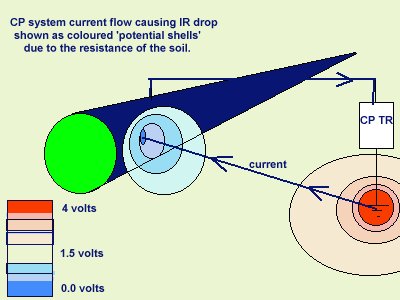
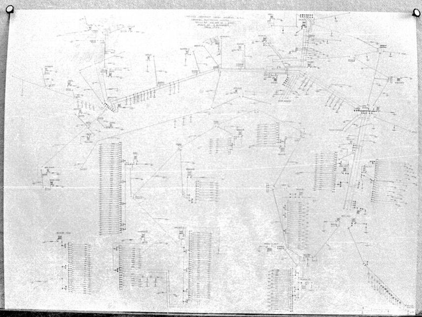
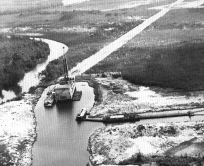
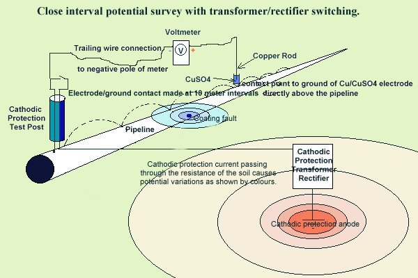
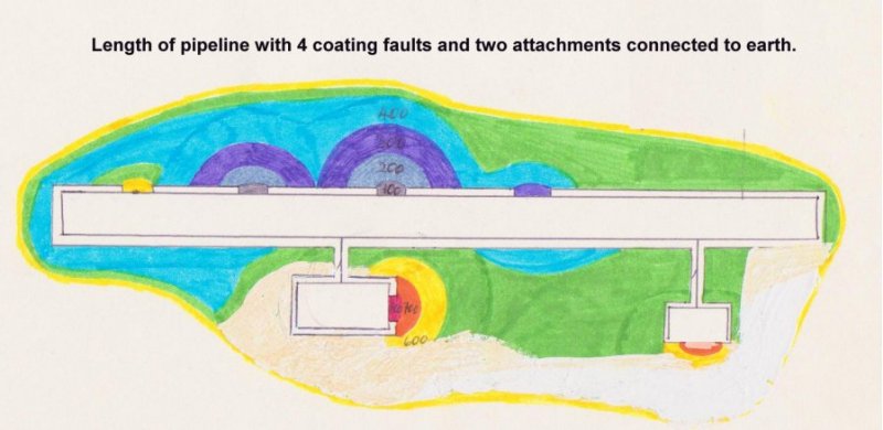
The picture above is an equivalent circuit diagram of the cathodic protection systems that were preventing corrosion over an area of tens of thousands of square miles of pipelines serving a major oil and gas production company.
The chemical composition and electrical conductivity of the ground can span a vast range and can include environments such as sea water, deserts, freshwater swamps, arable (fertilised) land, etc. etc. Climatic effects cause variations in the temperature, and depth of cover causes pressure variations which effect the reaction, adding yet more indeterminable factors in the reaction.
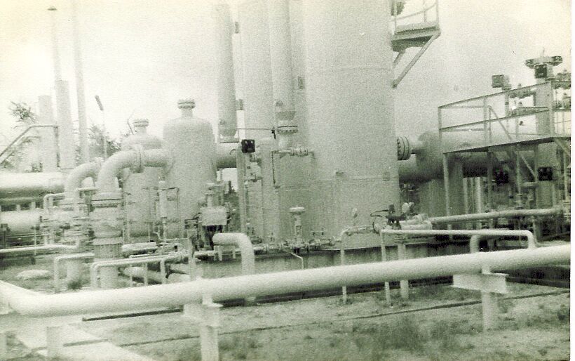
Cathodic protection of such subjects as gathering stations (shown above) and storage tank bases is relatively simple but as the size of the structure increases, it extends through electrolytes of different nature and the reaction at each interface varies. Offshore oil rigs, for example have different temperatures and pressures at the sea bed to those at the surface, and studies of these conditions have shown that they have substantial influences on corrosion.
UNDEFINABLE ELEMENTS
Pipelines are more complex, and can be regarded as many interface reactions connected together, in parallel.
The metal element, of the reaction, can be well defined, as this is specified to a high degree by the designers. The coating material is carefully designed but it is generally accepted that no coating can be perfect, and the faults (or 'Holidays') introduce the first indefinable element to the system.
During the construction of a pipeline, all possible measures are taken to detect and repair coating faults, so it follows that the location and size of those remaining are unknown and not definable. It is possible to calculate the theoretical resistance of a perfectly coated pipeline, given the specification of the coating and dimensions of the pipeline, but it is not possible to calculate the resistance of the coating of an actual pipeline.
The electrical current measurements, taken during routine cathodic protection monitoring, show that there is little resistance in the total coating of a pipeline and this can be explained by the difficulty in quality control during coating operations and preventing damage during the construction period.
Perfect coating would prevent any output from the CP system but undetected coating faults provide paths for cathodic protection current. We, therefore, know that there are many unspecified metal-to-electrolyte interfaces present on an average pipeline.
The electrical resistance of the pipeline metal itself can be calculated, and is found to be very low. The effect that the pipeline resistance has on the complex current paths and variation in potentials, is found to be so small that it can almost be ignored.
FURTHER COMPLEXITY
Each coating fault is a metal-to-electrolyte interface which is capable of a different reaction, electro-motive-force (EMF) which cannot be measured as it is in parallel with all other EMFs on the same section of pipeline.
The magnitude of the current from each of these is dependent on the earth resistance immediately adjacent to the interface, and the current direction is the result of the combined effects of all the resistances and electrical pressures caused by all the other EMF's.
Although it is simple to understand each corrosion cell and the mechanism of corrosion itself, the reality of applying the science, to the field, becomes immensely complex.
This becomes more obvious when the circuit has been subject to computer modeling as discussed later.
To be effective, cathodic protection must reduce the metal at each single interface, to below it's corrosion potential. This is not too difficult to achieve, as each interface is part of the same structure, which has a very low electrical resistance. The difficulty is knowing when all the interfaces have been reduced to below their corrosion potential in relation to the electrolyte in their reaction vicinity.
OVER PROTECTION
There are several other problems, however, as too much current passing onto a steel surface can cause embrittlement, which under certain circumstances can be as detrimental as corrosion itself. This is manifest in such applications as the protection of the external surfaces of drill pipe casings, where a considerable amount of cathodic protection current is used.
Another fear of 'over-protection' is that of cathodic disbondment of the coating. This happens when the coating manufacturers specifications are exceeded. Cathodic protection current passing onto the metal causes the release of hydrogen which disbonds the coating. In reality this is rarely a problem.

The current will only pass onto the metal at a coating fault, and the density of the current will depend on the size of the coating fault and the current locally available. As the current blows the coating from the metal, the volts drop at the interface will decrease, and equilibrium will be reached with a very small increase in additional disbondment.
If there is no coating fault, then no cathodic disbondment will occur, as recognised in the British Standard Code of Practice for testing the coating manufacturers specification. This requires a specific size of coating fault on a steel coupon, to be subjected to an increasing voltage over a specified period. The test cannot be carried out on a coupon with perfect coating as the disbondment is observed under the coating at the edge of the fault.
These matters will be covered in detail later in the course
THEORY V PRACTICE
We simply want to stop corrosion but we need to know when we have succeeded. Cathodic protection is immensely successful, and cost effective, but every leak is a demonstration that we have not applied it correctly.

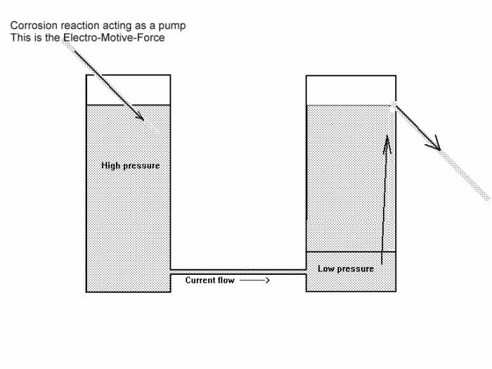
Before going any further it is necessary to imagine electricity and this has been likened to water pressure, with containers connected by pipes to allow current to flow.
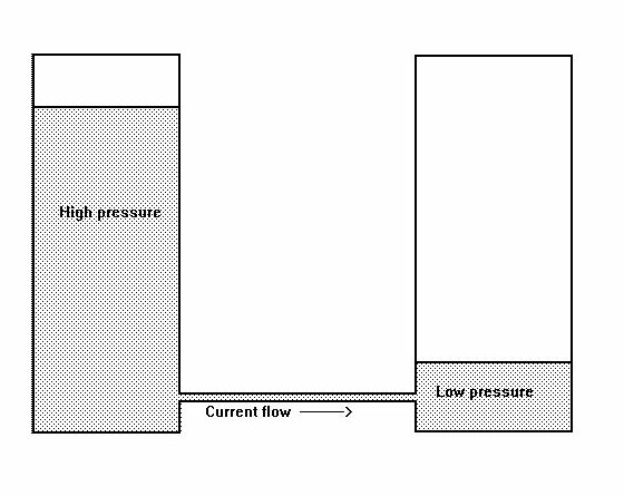
However, it can be seen that the levels would equalise as soon as enough water had run from one container to the other. No current would then flow.
If water was added to the higher container at the same rate that it is passing through the connecting tube, then the current will continue.
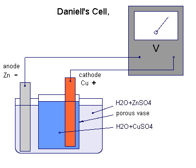
This is similar to a dry cell battery which is, infact a corrosion cell. The current will flow through a conductor when the two poles are connected in the same way that water flows through the connecting tube at the bottom of the two containers.
When the reaction energy has run out, the battery is dead and the potential levels are the same at each pole.
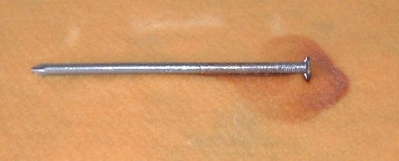
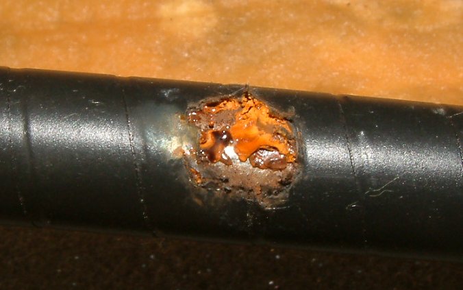
A corroding nail is similar in that the corrosion current flows from the anode of the nail, into the damp cloth and then goes back through the cloth to the cathode of the nail.
The corrosion reaction on the nail can be forced in a variety of ways to be defined in this course.
Refering back to the water analogy, it is important to understand that the pressure is caused by the height of the water in each container and not the weight. The water will fill any connecting tube and then the pressure downwards will be greater in the vessel which has the highest level. The reason for this is obviously due to the imbalance between the pressures in the two containers and electrical potentials have the same tendency when connected by conductors.
This is fine when visualising a simple circuit such as a single corrosion cell or a dry cell battery connected through a light bulb, but in a cathodic protection circuit, or when corrosion takes place on a pipeline we have no means of measuring each separate cell in this way.
If we examine the technique that is used in the laboratory then it becomes clear that provision has been made to eliminate outside influences in this 'open circuit measurement'.
This is not possible in cathodic protection field work, and yet laboratory derived theories are applied to readings obtained in the field.
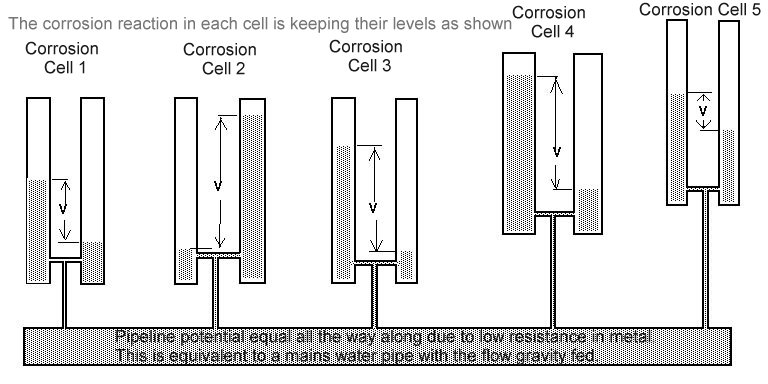
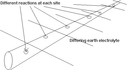
The situation on pipelines is that there are many corrosion cells, all connected to the same metal and yet each having it's own corrosion reaction. This can be imagined like this.
It can be seen that it is impossible to measure the pressure differences in each cell by making a single connection to the common reservoir at the bottom. However it would be possible to stop the flow of water in each of the cells by continuously making the water level equal in each pair of containers.
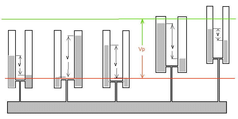
However, it can be seen that the pressure measurement in such a system would need to be between the lowest water level and the highest water level in the whole system.
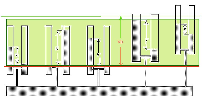
This is achieved in cathodic protection by flooding all the containers as shown in green. The current then stops flowing between each pair. Because of the nature of electricity this requires that current is drained from the pipeline and pumped into the ground in sufficient quantity to 'fill all the containers' or overcome the corrosion reaction potential (EMF).
link to page showing water containers to demonstrate electrical potentials and in relation to pipeline cathodic protection
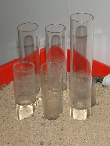
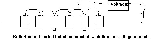
The difficulty in making this voltage measurement is shown in the demonstration with water holders buried in sand.
We can measure the level of the water against the level of the sand.
We cannot see the bottom of the containers but in this case some are connected to others by a glass tube through which the water can pass.
Water can pass between some of the visible containers to others in the same way as corrosion current.
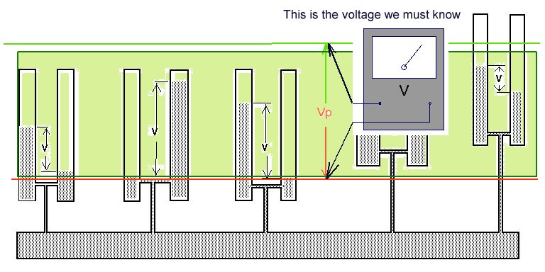
We can never know if the corrosion current has been stopped when (whole system is in equilibrium) as we have no reference to zero potential. It is out of sight and reach!
In the same way, we cannot know the EMF (water level) of each corrosion cell. We can only measure the voltage between the potential of the ground and the potential of ALL OF THE METAL. That is the equivalent of the level of all of the water in the containers. We do not know how deep each containers is and we do not know which are connected.
The established method of measuring the effectiveness of cathodic protection is by recording the voltage between two variables. This cannot determine if corrosion has stopped.
Open circuit measurements
The term 'open circuit measurements' was acknowledged by Dr Peabody of NACE when recognising the problem that was termed 'the IR drop in the soil'
Natural corrosion cells are much different from those set up in a laboratory, as they can be physically minute or large. Large corrosion cells can contain micro-cells within the same area where anodic areas completely surround cathodes or vice-versa. When studying such cells, we are not able to separate the component parts, and the measurements have come to be known as 'open circuit measurements'.
This type of measurement involves connections to the electrolyte as well as the metal and this requires the use of an electrode. There is a danger that this will introduce another EMF into the circuit, by the reaction between the electrode and the electrolyte. We therefore use an electrode in a solution of its own salts, which has a known reaction EMF. We can then make a connection between the electrolyte in the cell and the earth electrolyte, in the hopes that there will be no electrical disturbance to the measuring circuit.
In the laboratory, this disturbance is prevented by the use of a glass capillary filled with inert gel, which is used as a conductor from the reaction interface to the reference electrode. The reference electrode is a metal in a saturated solution of its own salts, as this has a known reaction potential. Reference electrodes are related to each other by known voltages and are used as international standards.
Without this consistency it would be impossible to evaluate the reaction, develop theories or design cathodic protection systems etc.
Unfortunately, it became the practice to apply laboratory principles in cathodic protection field work.
This subject can now be studied in greater detail by computer modeling which makes it clear that the fixed potential is normally that of the pipeline metal, and the variation in the measured voltage is due to the different potentials elsewhere in the measuring circuit.
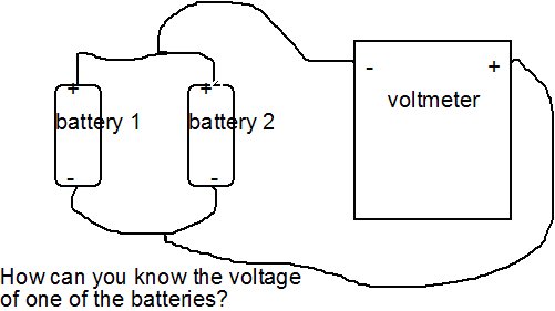
Imagine that we require to know the voltage of two dry cell batteries which are arranged in parallel. That is to say that each is in connection with a common conductor to the positive pole and another common conductor (the ground)to their negative poles.
Both conductors would carry equilibrium current according to the reaction within each battery and the voltage between the two conductors could be measured by connecting a meter between the two. Unless the two cells are separated, it is impossible to evaluate the voltage of each battery. Even this is not as complex as the expectancies of cathodic protection monitors.
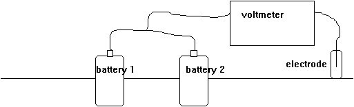
If we take two batteries and half bury them in an electrolyte with their positive poles exposed and connected, we have two corrosion cells in closer condition to those found on a pipeline.
A circuit drawing of this arrangement will show that current will pass through the ground to equalise the pressures caused by the interface reactions within each battery.
We must now try to evaluate the reaction within each battery using a high resistance voltmeter and an electrode. We cannot break the circuit or separate the batteries but connections can be made to the metal or the electrolyte or both. It will be seen that we are only capable of measuring voltages across various spans of the circuit, and cannot establish a reference within that circuit. The laboratory techniques cannot be applied to these conditions as there are too many variables which are impossible to evaluate.
If we increase the number of half buried batteries connected together, we improve the similarity to a pipeline, but in order to be more realistic, we must include some which have their positive poles buried. This has been shown earlier in this page.
The complexity of the situation is now apparent and what seemed to be a simple measurement, now seems almost impossible.
A circuit diagram of the complex arrangement will show that a different voltage will be measured with every new position of the electrode, and this is born out in cathodic protection field practice. It is especially obvious on pipelines which are not connected to cathodic protection systems and which have poor coating.
The different voltages are due to the variety of potentials at each pole of the voltmeter. These can be caused in many ways, as described later, but it is important to realise that they are all components of the voltage shown on the meter. It is possible to eliminate them in the laboratory but not in the field, therefore they must be evaluated and considered in the analysis of survey results.
The problem is even more complex when cathodic protection is introduced as this is an additional voltage which is superimposed over all the others. Being designed to drain charges from the whole of the
pipeline, it has an effect on the equilibrium of all the other electrical influences. However, the dynamic effects of an impressed current system can be removed by taking voltage measurements immediately after the system has been switched off.
This cannot be achieved where sacrificial anodes are used, unless they have a special facility designed for this purpose at construction stage.
The voltages obtained between the pipeline metal and a randomly placed electrode have a certain amount of value when compared to others obtained from connections to the same pipeline. This is because of the very low electrical resistance in this part of the corrosion and cathodic protection circuits.