Cathodic Protection Training Course
INSTRUMENTATION FOR MONITORING CATHODIC PROTECTION
The history of cathodic protection technology is dominated by development of electrical measuring instruments and how this was perceived by engineers.
THE GALVANOMETER
Digital instruments were not readily available until the 1970's and cathodic protection measurements were carried out with a variety of electrical meters which were based on the galvanometer.
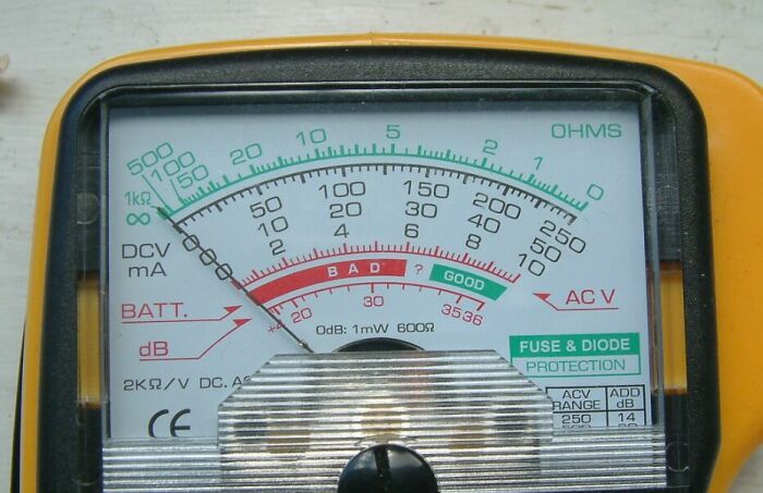
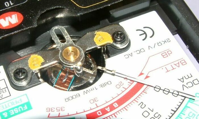
These instruments work on the reaction of a magnet in an electric field against the elastic effect of a hair spring.
They are less rugged than digital instruments and more difficult to manufacture. They also require a considerable amount of current to move the indicator needle.
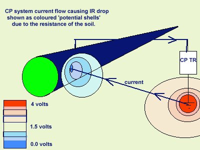
The amount of current drawn by this type of instrument is sufficient to cause a depression in the potential of the soil in which the electrode is
placed.
It can be said that the current flowing through the measuring circuit causes its own IR drop.
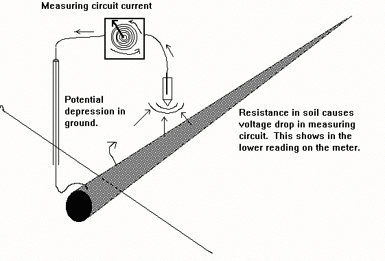
This potential depression can be measured using two electrodes and a digital voltmeter.
This 'volts drop' in the measuring circuit caused substantial inaccuracies in the measurement, and the readings were shown to be lower than the true voltage. This is the opposite effect to that of the 'IR drop in the soil' which is caused by the passage of the cathodic protection current.
During the period in which these meters were used, the fact that the readings were less than the criteria, encouraged operators to blame instrument inaccuracy when protected criteria could not be achieved.
All the time that a needle was moved against a hair spring, at any time in the measuring process, this required sufficient current to be affected by any resistance in the measuring circuit. Instruments which were extremely sensitive had to have extremely fragile mechanisms which were unsuitable for rough field use.
The error in the measuring system tended to give the impression that sections of pipeline were not protected and engineers worked to increase the protection on these sections. They found that many sections of pipeline could not be 'protected' as it proved impossible to increase the output of the cathodic protection system enough to show the required voltage on the meter.
A formula was recommended to correct readings to an increased value, in proportion to the internal resistance of the voltmeter. This formula corrected the readings upwards towards the required criteria, in contrast to the present correction that which is obtained by switching the CP current off and is a correction downwards.
NUL-BALANCE METERS
Attempts were made to design specialised instruments which balanced out this error with an opposition EMF supplied from an internal battery. The idea was that if they worked on a balancing process when the actual
measurement was made, then they would draw no current. Some of these instruments became quite complex but they all drew current during the original balancing operation, and hence none reached the accuracy which is
possible with a digital meter.
The designers seemed to have missed the point that the current drawn, to set up the balance, created an error which was carried through the whole measuring operation.
The complexity of operation of the balancing meters required more care and understanding by the operators, and the instruments were not as rugged
as the simpler ones of the day.
Instruments appeared with more and more dials, switches and adjustments but this resulted in less and less personnel who understood how to use them. It also had the adverse effect that the amount of time to take a single reading with such an instrument, precluded the possibility of taking 'immediate off potentials'.
There was then the problem of measuring the EMF which had balanced the measuring circuit. This had to come from a dry cell battery which would not have a constant potential as the current drawn, to balance the
circuit, would drain the battery each time of use.
Some instruments were then marketed with a more constant (laboratory tested) battery built in, with which to balance the, commercially available, dry cell.
The problem that still remained, was to establish a potential value, within the meter, against which a reliable voltage could be measured.
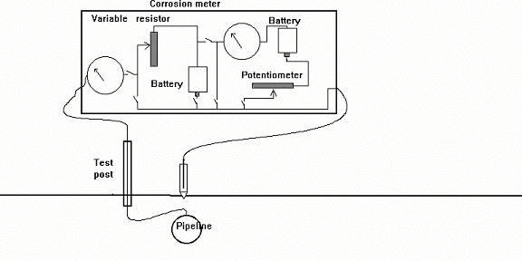
Sophisticated variable resistors were built into some instruments and it was claimed that an error free voltage could be measured by a complex procedure of balancing potentials using two galvanometers, two sources of DC charge and a variety of switches, variable resistances and a component called a potentiometer.
On examination, the 'potentiometer' turned out to be a
variable resistor which had been calibrated to give
a reading on a mechanically driven digital dial.
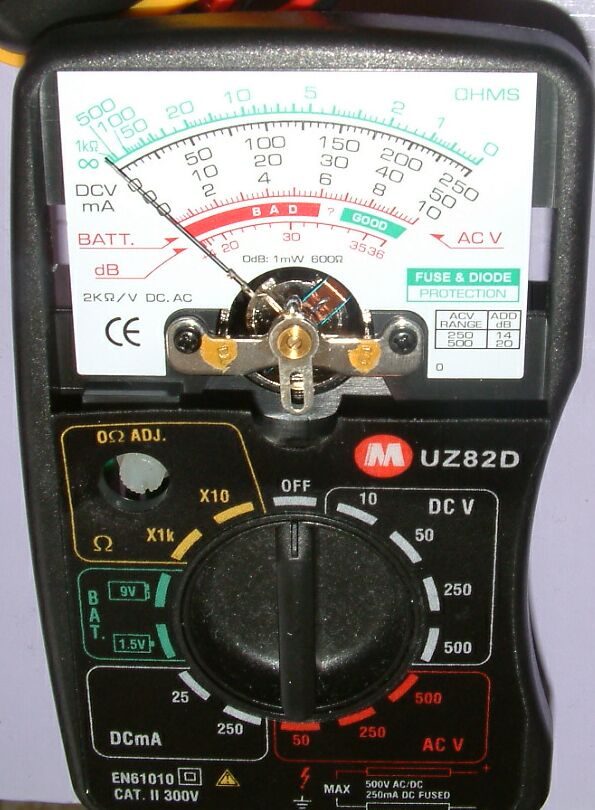
DIGITAL METERS
The availability of digital instruments removed the downward error which had been caused by the volts drop in the measuring circuit and allowed increased voltages to be obtained, because they dramatically reduced the amount of current flowing.
The solid state electronics of today's meters only require a tiny amount of current to make a reading and the resistance in the measuring circuit is greater by an order of magnitude than the resistance in the circuit to be measured.
Using a digital voltmeter with an impedance of 7 to 10 mega-ohms per volt ensures that the current flowing through the measuring circuit is not sufficient to cause a potential depression in the earth in which the electrode is placed.
When using galvanometers, the error in measuring had helped to balance out the IR drop in the soil which, at present, causes optimistic readings.
In fact it was the advent of digital metering which bought the question of the cathodic protection criteria sharply into focus.
Pipelines began to fail in areas where digital voltmeters had shown that the pipeline had achieved a voltage difference of -0.850 mv with reference to an electrode placed immediately above the pipeline on the ground surface. It is doubtful if this value would have shown on a galvanometer which often required the ground contact to be watered to allow sufficient current to pass through the metering circuit to activate the magnet against the hairspring.
This inaccuracy was not an advantage, but did have some tendency to balance the inherent error in the measuring technique.
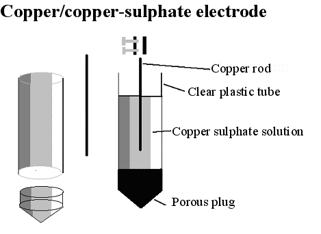
THE COPPER/COPPER-SULPHATE ELECTRODE
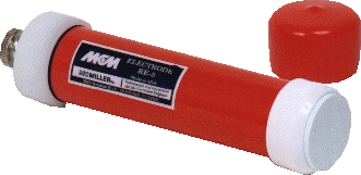
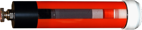
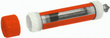
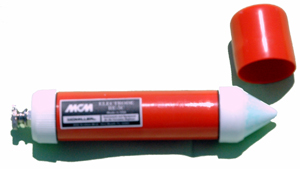
It is now necessary to examine the electrode, which is merely a copper rod immersed in a saturated solution of copper sulphate.
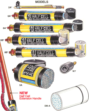
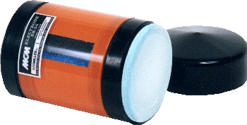
There are many available on the market as this selection shows.
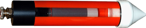
But a half-cell for cathodic protection monitoring can be made by anyone. Students are required to made a half-cell as part of the practical work of this course. The copper/copper-sulphate electrode is regarded as a reference electrode as, under laboratory conditions, it can be used as a known potential against which to measure a voltage.
It cannot be regarded as a REFERENCE POTENTIAL in cathodic protection field work, where it is simply a method of contacting the ground.
In the laboratory, the reaction within the electrode, has a known value and the voltage reading on a meter can be used to calculate the potential on the other pole of the meter.
'Half-cell'
In cathodic protection field work, the electrode is simply part of the measuring circuit, and has no mystical powers. Current can pass through the electrode in either direction to or from the electrolyte without a
surface reaction which is peculiar to the external electrolyte at that location.
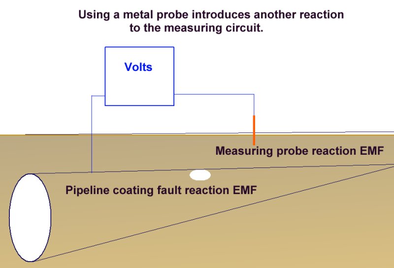
It is therefore better to use a standard copper/copper-sulphate electrode than to use a simple metallic probe which would introduce yet another variable, (an undefined EMF) into the measuring circuit.
There are many uses for the electrode, but in order for it to be used as a reference potential it must be used in conjunction with an isopotential cell or in accordance with very strict formal procedures (that will be taught in this course) similar to the discipline that is imposed in the laboratory.
LABORATORY USE
An example of laboratory discipline can be seen in the British Standards Institute, Code of Practice for testing paints and coatings for their cathodic disbondment potential. This code of practice specifies that the reference electrode is placed exactly 10mm from the metal to electrolyte interface, at a coating fault which is deliberately made on a test piece.
The pH, temperature and pressure at the time of the test are specified, as are the period of time and the stages of voltage increase.
Gross errors can be readily demonstrated during this procedure by simply moving the reference electrode.
Another example is shown in the book 'ELECTROCHEMICAL PRINCIPLES OF CORROSION' A Guide for Engineers, by Dr LL Shrier for the Department of Industry of Great Britain. The illustration on page 11 shows a laboratory experiment referred to as a 'Daniel cell' which is an arrangement to ascertain the rate of transfer of charges in a spontaneous corrosion reaction. This shows clearly that the reference electrodes have the sensitive end of their glass capillaries at the immediate interface between the metal and the electrolyte.
The reason for this is that current passing through an electrolyte meets with a resistance which causes a voltage drop. If the electrode is placed randomly, then an undefined variable is introduced into the calculation.
The use of an inert gel in the capillary prevents the introduction of a chemical disturbance of the subject interface.
CARE NECESSARY DURING FIELD USE OF THE ELECTRODE
There is much confusion amongst field operatives in cathodic protection, as to the properties and usage of the 'half-cell'. One engineer wrote that it is capable of 'scanning a section of pipeline'.
It is quite clearly not capable of scanning anything, it simply makes contact with the ground, forming one link in the measuring circuit.
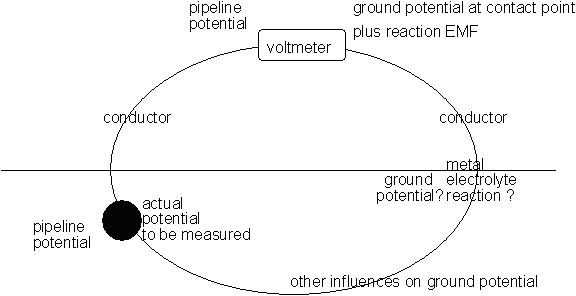
Measuring Circuit
MAINTENANCE OF THE ELECTRODE
A lot of fuss has been made by some engineers about the cleanliness of the copper sulphate solution and the purity of the metal within the electrode but this only has 1% to 2% effect on the readings which is an
acceptable error by comparison to that caused by moving the location of the electrode, which can introduce an error of 100% or more of the actual value.
Never the less, it is worth making sure that the copper rod is pure and clean and that the solution of copper sulphate is saturated and pure. Distilled water should be used to dissolve crystals of copper sulphate
making sure that there are always some crystals remaining in the clear plastic tube.
THE POROUS PLUG
A matter which is rarely bought to question is the nature of the porous plug which might introduce other components into the solution. Laboratory electrodes will have neutral plugs but those used in cathodic protection
field work have wooden or plaster plugs which can contain either acids or alkali in their composition. There seems to have been little attention paid to this and it would probably not cause a substantial error into the measurement.
GROUND CONTACT
Errors can be introduced by poor contact between the electrode and the electrolyte. In very dry conditions on hard concrete or dry hardened sand there might be such a high electrical resistance that it has a significant
effect on the reading, even when a very high impedance digital meter is used.
CONNECTION TO THE METER
Poor contact between the conductor lead and the pole of the meter can cause errors and fluctuations if there are metal oxides and damp associated with these connections.
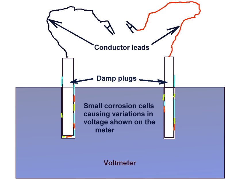
These phenomena will be caused by the micro-reactions taking place between the films of moisture and the variety of salts and metals.