Cathodic Protection Training Course
MONITORING
Measuring the effects of cathodic protection
Cathodic protection has been extremely cost effective since first used, but there have been instances throughout its history, where corrosion failures have occurred in spite of it's use.
The problem is to measure the effectiveness of cathodic protection. Corrosion is electro-chemical and this suggests that electrical metering can be used for short term monitoring.
The simplicity of the circuit of a single corrosion cell would tend to suggest that there is a simple means available to make the required measurement.
Standard reference electrodes have a recognised and known potential which can be used as an electrical datum point against which to measure other potentials, in a laboratory.
We normally measure VOLTAGES which are the differences between two potentials.
This causes confusion because the readings are commonly called "potentials", where in fact, either of the two potentials can be regarded as zero and the other will be either higher or lower. The meter will show positive or negative values according to the polarity of the connecting conductors.
Cathodic protection theory dictates that the metal must be reduced to below its corrosion potential IN RELATION TO A STANDARD REFERENCE POTENTIAL. These potentials can be measured in a laboratory where it is possible to control all elements of the circuit, but it has proved impossible, so far, to measure the required potential in field work.
The problem with field measurements, is that the earth at one location has never exactly the same potential as the earth at another location. In a laboratory, the electrolyte is contained in an electrically insulated container and the currents are all in closed circuit and related to the corrosion reaction. The potential of the electrolyte can be measured at the reaction interface by the use of a glass capillary containing an inert, but conductive, electrolyte such as agar-agar gel. This cannot be achieved in field work, although a close approximation has been achieved by Dr Prinz of Rhurgas, in Germany.
Field readings taken and analysed in the established way are not related to each other, except through the low resistance of the pipeline itself. This is easily demonstrated by a simple calculation base on Ohms law as follows.
Take any sample readings from a typical pipe-to-soil "potential" cathodic protection survey and work out the amount of current that must be passing through the pipeline between any two cathodic protection test facilities.
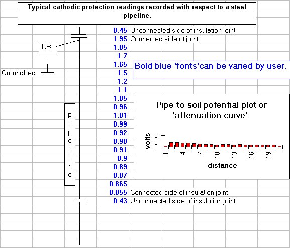
These readings are from a real cathodic protection record in which the technician measured the voltage between the pipeline metal and a Cu/CuSO4 electrode contacting the ground close by.
The way that the graph shows these readings would be interpreted by an electrical engineer to mean that the potential of the pipe metal was different at the different locations.
A cathodic protection scientist will confirm that the electrode has a known reaction and can be regarded as a reference potential, and therefore the metal of the pipeline must be the other potential against which the meter measures the voltage.
A cathodic protection engineer will say that they never measure the current in a pipeline in this way. For some reason we cannot apply Ohms Law in these circumstances.
The reason why cathodic protection engineers say this is because the current calculated using Ohms Law will be found to be ridiculously high, to the extent of being unbelievable.
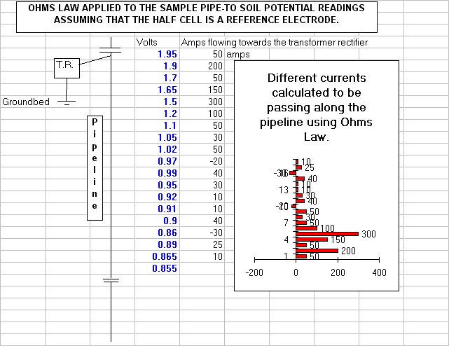
For example, a span of 24"diameter steel pipeline ten miles long will have a resistance of about 0.001 Ohms, depending on the wall thickness, and the readings at either end of the span might be -0.950 volts and -1.250volts. This would not cause alarm, and would be plotted on an 'attenuation curve', without too much comment. However, calculation shows that, if the 'half-cell' (electrode) is truly a reference, then there is a volts drop of 0.300 over the ten mile span. This seems reasonable until it is realised that with such a low resistance there must be 300 amps passing through the pipeline. Something is quite clearly wrong with the measuring system or the theories.
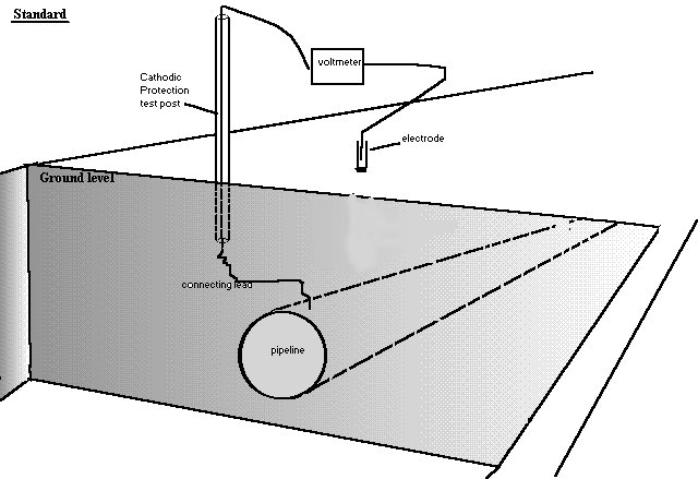
Cathodic protection engineers produce graphs that display voltages relative to distance along the pipeline. The voltage is measured between the pipe metal and a copper/copper-sulphate electrode placed in contact with the ground. The connection to the pipeline is not altered during the survey of one section of pipeline but the ground contact position is stepped along that section, as close as possible to the pipeline metal.
There are millions of voltages on record throughout the world that are used in the design, commisioning and maintenance of all cathodic protection systems.
One use of such graphs is known as an 'Attenuation Curve' and it is thought by the designers, that this shows the extent to which the cathodic protection current reaches each span of pipeline between impressed current transformer rectifier 'Drain Points'.
The current is thought to extend to the point at which the pipe-to-soil voltage is -0.850 volts at which point it travels back along the pipeline towards the 'Drain Point'.
This can be drawn in a simple equivalent circuit drawing, and there are many in CP reference books and scientific papers.
However, when such circuits are actually made to the specifications shown.... they do not show the same characteristics as in practical field work.
A more realistic model is shown by CPN technology in the spreadsheet pictured below.
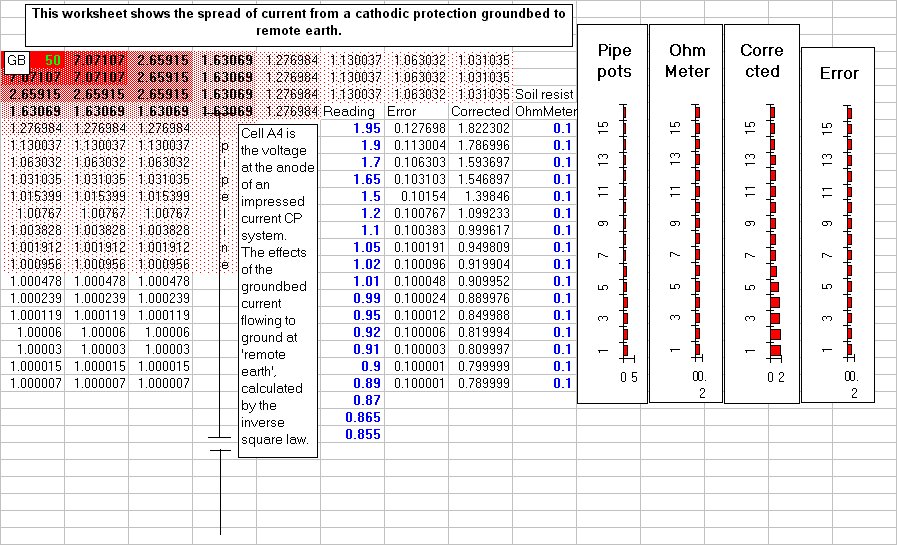
This shows that it is the ground potential that we are measuring with the pipe-to-soil measurement in cathodic protection work.
Cathodic protection scientists still insist that the potential of the copper/copper-sulphate electrode is constant and therefore it can be used as a reference potential gainst which to measure another potential displayed as a voltage.
To them, the baseline of the 'Attentuation Curve' graph is the potential of the reference electrode. The potential of the pipeline metal is the variable that is plotted. Cathodic protection designers still use this principle when designing and testing temporary facilities.
Field engineers and electricians know that the half-cell is NOT a reference potential, when used in this way, and consider it stupid to make calculations as suggested based on Ohms Law.
The introduction of the 'off potential' measurement and the continuing search for better and better methods of sychronising GPS and data loggers is proof that CP specialists are still trying to produce data that relates to the voltages between a 'reference cell' and the pipeline metal. They are attempting to remove the effects of the electrical flux in the electrolyte in which the pipeline is submerged. The voltages that are being recorded with all of these sophisticated techniques in place, still cannot be analysed using the basic laws of electricity.
The pipeline and the trailing conductor have a constant resistance for the whole of each span recorded as the measuring current has to pass through the same metal path. The only value that changes is that of the potential of the ground at the point of contact with the half-cell. The cathodic protection scientists and designers regard the half cell as a reference potential of constant value. Survey results are plotted showing the x axis as the baseline zero and then say that the voltages can be used to show the current distribution along the pipeline. If that is the case we can say that the current flow must follow the basic laws of electricity and pass from the high potential to the low potential at a rate determined by the resistance of that path.
No explanation has ever been offered by any established cathodic protection specialist to this simple question.
If the potential at point 'A' is 1.15volts and at point 'B' 0.95volts and we are refering both readings to the same conductor, why can we not apply Ohms Law?
The answer is that the voltages do not have a common zero. The graph is invalid for the purposes of establishing current flow within the pipeline metal.
The CP industry still believes that the half-cell is a reference electrode and that is why all CP records use this voltage. The resistance of each span of pipeline is included in CPN calculations but are not included in CP records viewed over the past 30 years. They are, however, available in all 'as built' construction drawings
held by the pipeline operators.