Demonstration
(Practical demonstration of how Cathodic Protection works)
Showing the limitations of the present survey techniques
and errors that make analysis of the data innacurate
This demonstration examines the electrical structure of the resistance in the soil and how it effects the readings shown on the meter.
The cathodic protection industry recognises that this feature is of importance but the resistvity surveys we are presently using add very little to any analysis of the corrosion status of the pipeline.
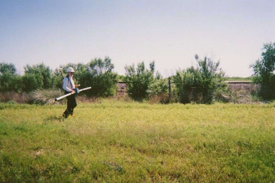
The device in use in the photograph above, measures the resistance of the soil in an area covered by the transmission and reception of signals.
The problem is that it includes any metal included in that area and if there are coating faults in the pipeline which fall in the area being scanned, they produce a gross error in the readings.
A more effective survey would be to take core samples in the backfill at locations of specific interest. Random core samples add very little to an analysis if the coating of the pipeline is of good quality.
Cathodic protection has two measurable effects. The potential of the pipeline is lowered because charges are drained from the pipeline. Scientists might argue that we are actually pumping electrons into the pipeline but we do not normally measure electrons, we view the effect they have on the meters that are available industry.
We can measure the effect of the passage of current onto the pipeline at coating faults using two copper/copper-sulphate electrodes and a digital voltmeter. This measures the potential difference in the ground between the two contact points.
see details of the origin of this type of survey here
The second effect we can measure is the potential profile of the area surrounding the area where we are grounding the charges.
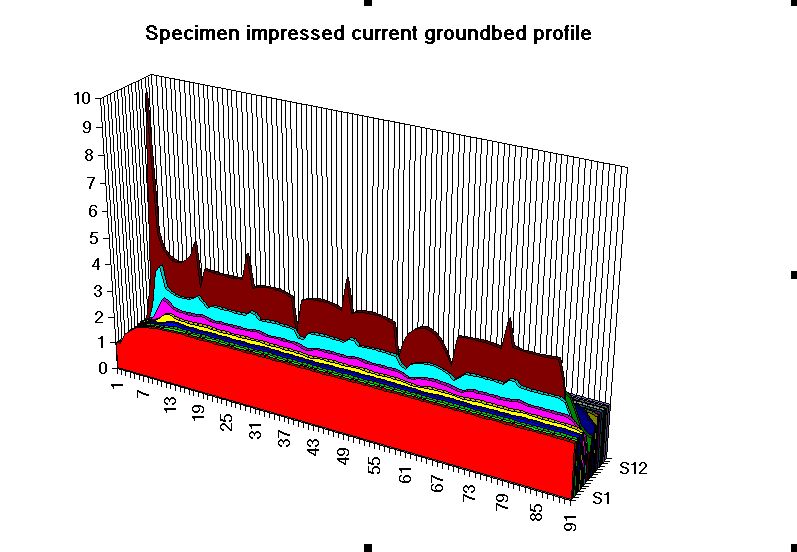
The above profile resulted from a grid survey at one end of an impressed current cathodic protection groundbed. The exact positions of each anode and relative states of effectiveness can be seen.
These two effects are caused by the cathodic protection current passing through the variety of resistances in the soil resulting in the 'potential gradients' that are detectable on the surface as voltages.
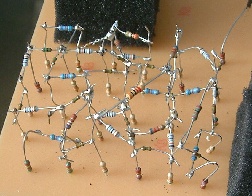
It is possible to imitate these effects using the type of resistors used in electronic circuits.
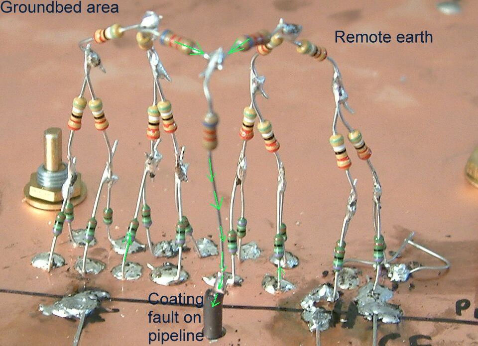
This equivalent circuit shows an arrangement of resistors soldered onto a copper board which represents the ground. It can be seen that the number of resistors in parallel reduces as the current travels towards the pipeline metal which is represented by a copper wire underneath the board.
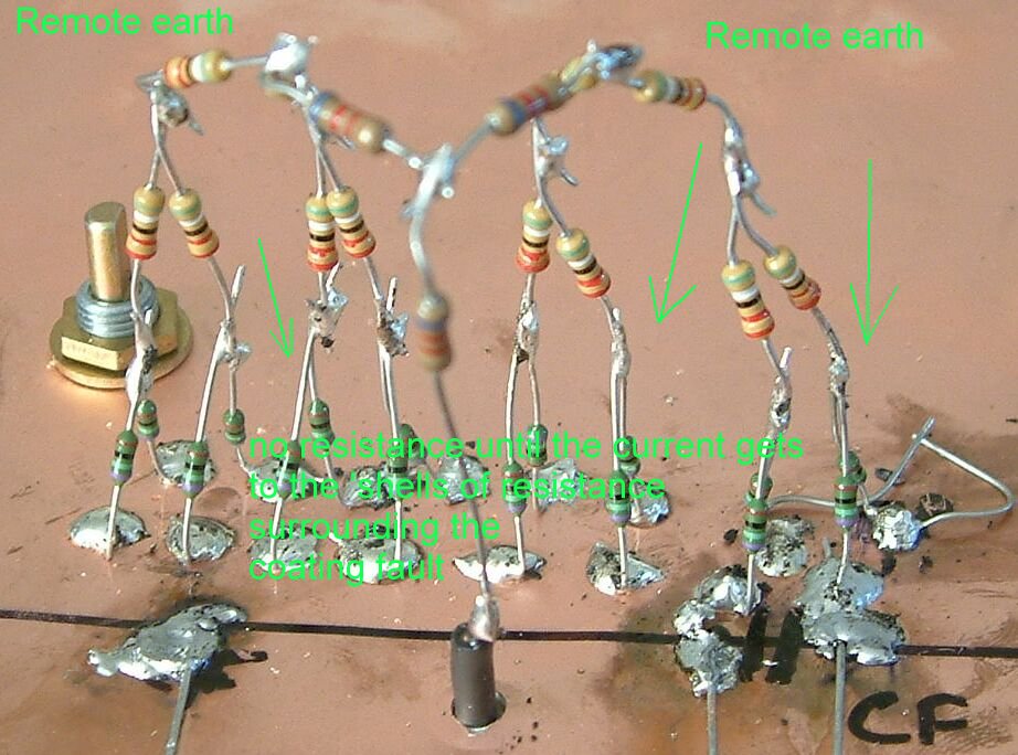
This shows the principle of 'remote earth' being an infinite number of resistors in parallel having no resitance at all.
This can be compared to an ocean of charges with rivers feeding in and pipes drawing water out. It is only when the suction is at a sufficient power that a small effect can be detected at the surface of a very shallow area of the ocean.
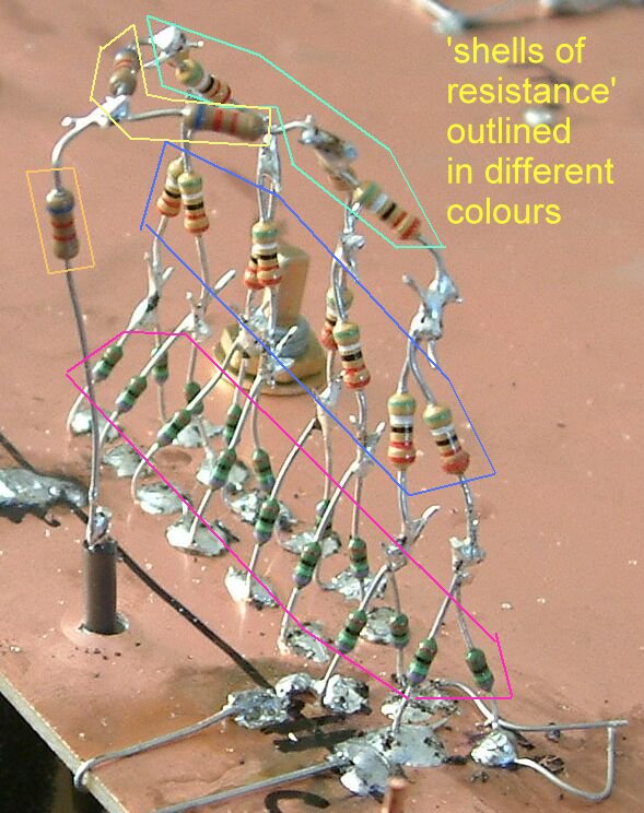
This shows the concept of 'shells of resistance' demonstrated in the first part of this presentation by the presence of the isopotential lines caused by the current flowing between the nails.
These were recognised in the early 1980's in the paper published by Dr Prinz et al.
This was at the same time as I first made this presentation.
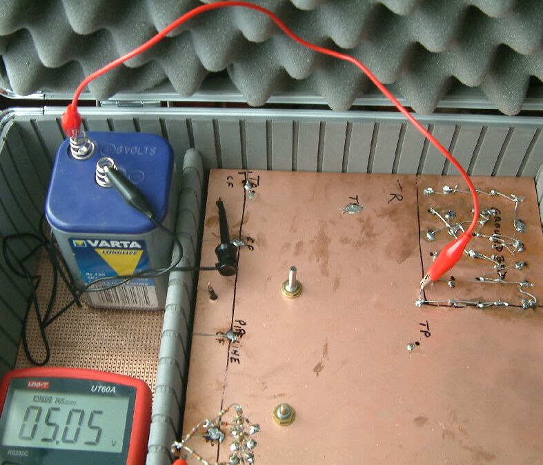
This shows the equivalent circuit of an impressed current cathodic protection system. A 6 volt battery is used as a source of current for convenience and safety.
This shows the current being impressed into the groundbed area where it has free flow to remote earth... the copper board.
The pipelines are represented by conductors underneath the board supported by high resistance pillars, each representing a coating fault.
Each of the three pipelines has the equivalent circuits of features to be found in the field while measuring pipeline cathodic protection voltages.
The equivalent circuit of the groundbed has only one layer but in reality it would best be represented by a hemosphere of resistors.
The electrolytic capacitor is useful for studying the 'polorisation decay' that is experienced when switching the CP system.
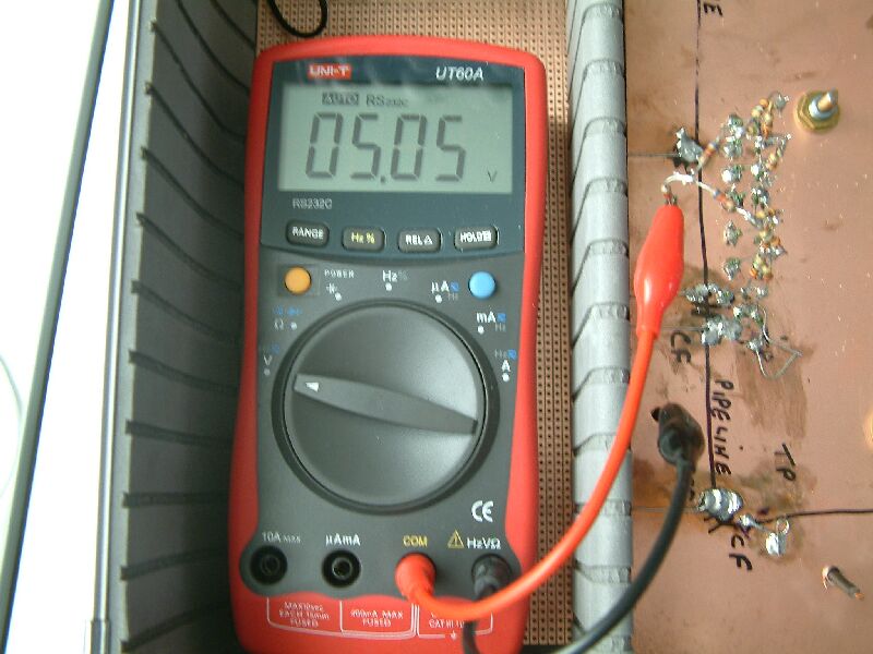
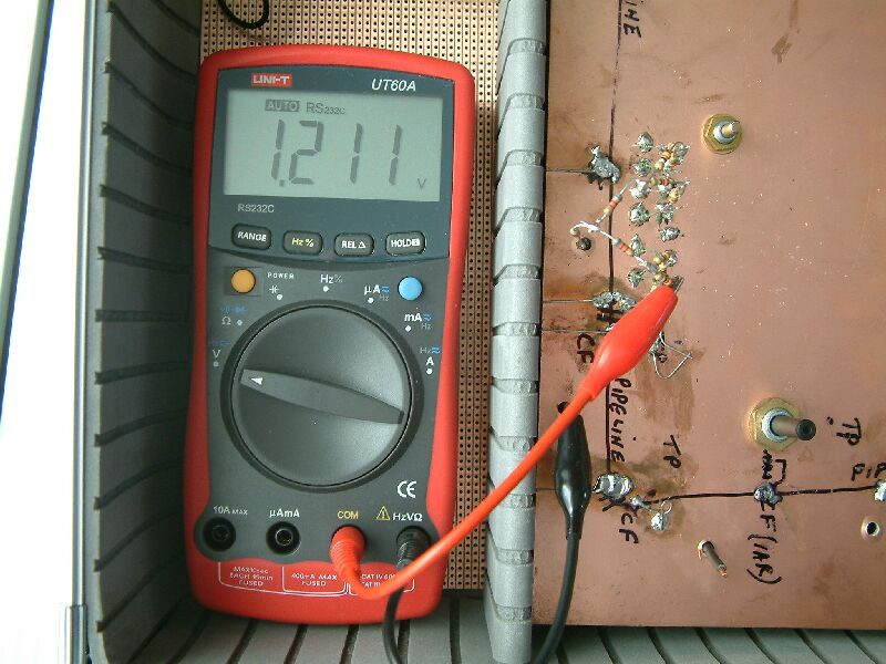
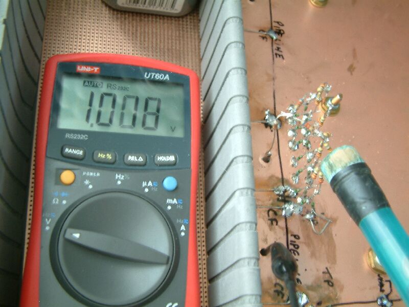
The first measurement is shown between the pipeline and the 'ground directly over the pipeline'. The voltage is high because of the combined 'shells of resistance' to remote earth.
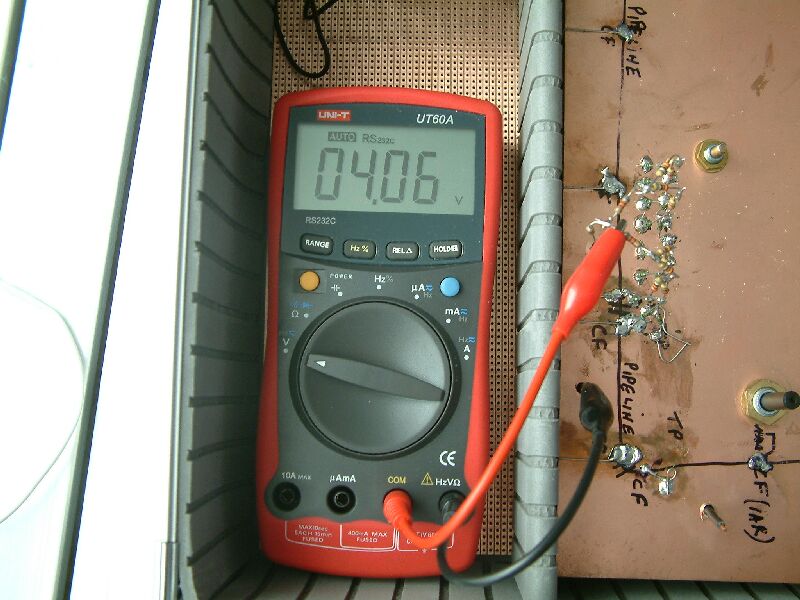
This measurement is closer to a coating fault on the pipeline and is within the aea effected by the IR drop.
When excavating to investigate a coating fault, the voltages reduce as the probe is placed closer to the metal of the pipeline.
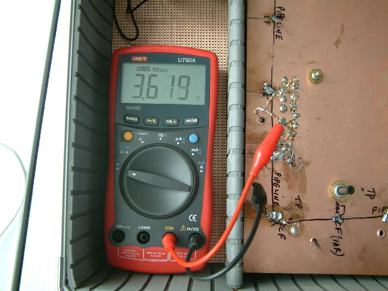
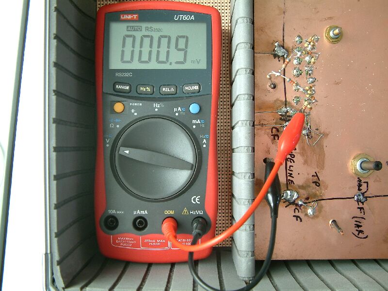
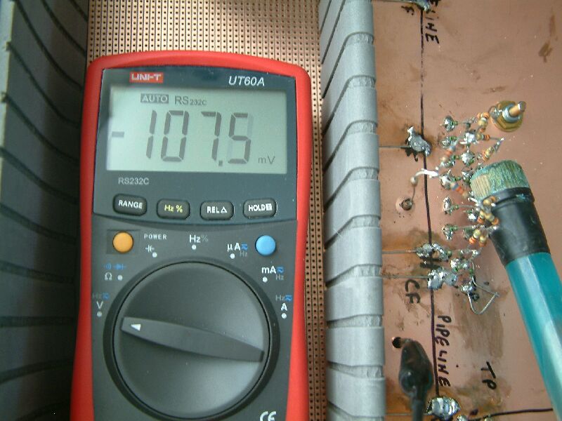
This shows that when the probe is placed very close to the pipeline metal the voltage is far below the present criterion for cathodic protection... even with the CP switched on.
We are now in the area recommended for the measurement to be correct according to the specifications required by the code of practice for cathodic disbondment tests.
A probe in this position in real life would have the effect of disturbing the status of the reaction being measured.
It is for this reason that a Lugin capillary is used in laboratory tests of this nature.
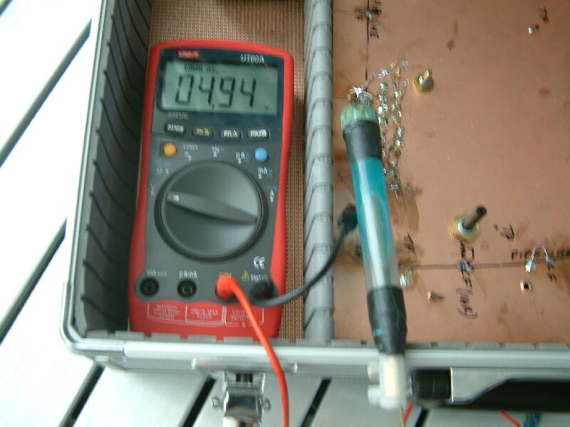
We can now examine if it is any advantage to use a half cell rather than a metal contact.
It can be seen that the values are reduced, due to the inclusion of the copper/copper-sulphate reaction included in the measuring circuit.
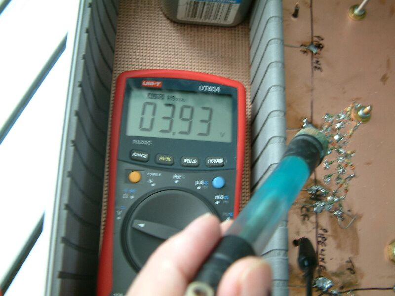
However the readings in the various positions are relative to the readings taken without the half-cell.
The only advantage being that we avoid a possible variable being introduce by the reaction of a metal probe to the salts within the ground.
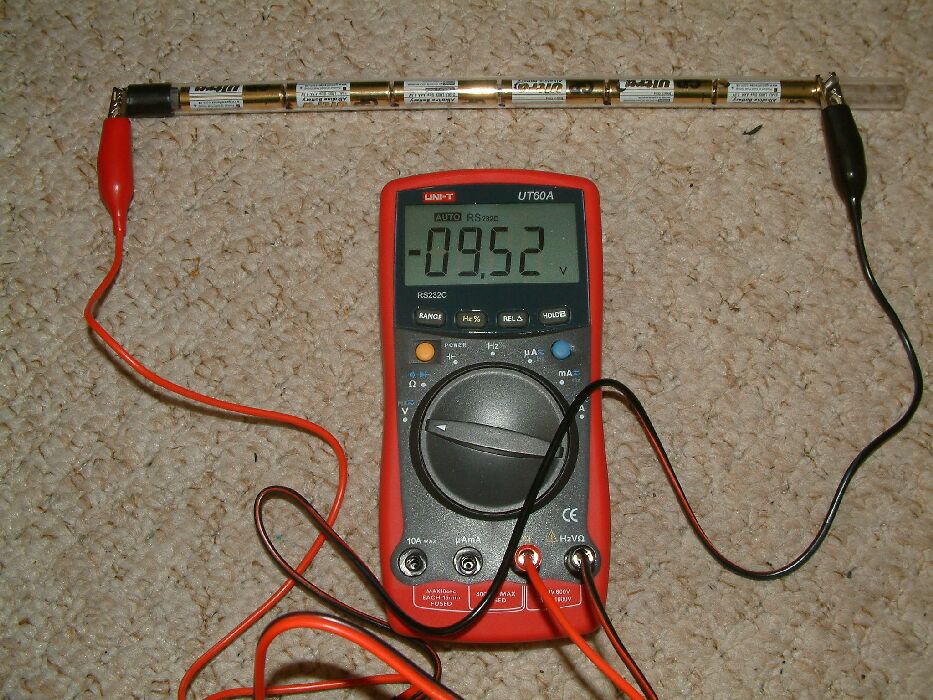
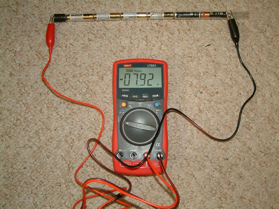
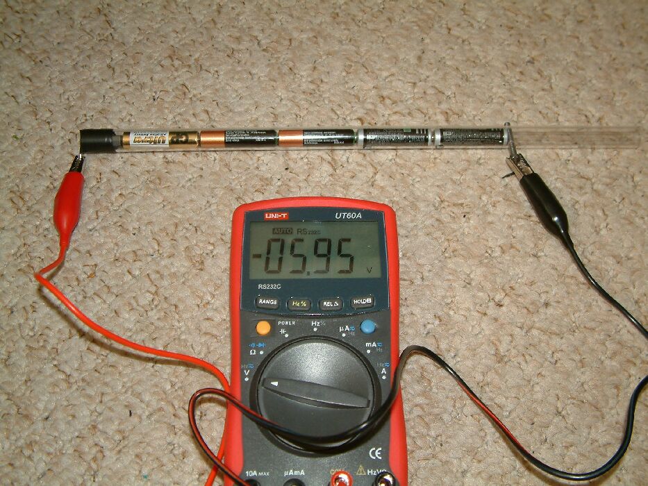
We are trying to measure the voltage (E corr) in a corrosion cell and for this purpose we can make an equivalent measuring circuit using dry cell batteries to represent the various voltages in series that make up this circuit.
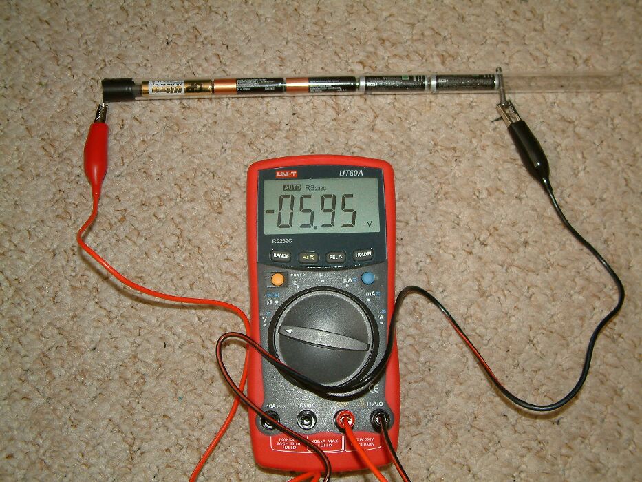
In the first picture we see the battery holder contains 5 new batteries and we can simply calculate the value of each by dividing the total voltage by 5. In the next picture one of the new batteries has been substituted by a used battery of unknown voltage. We can calculate it's value by taking the sum of the known voltages from the value shown on the meter and whats left is the voltage of the old battery.
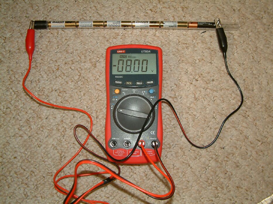
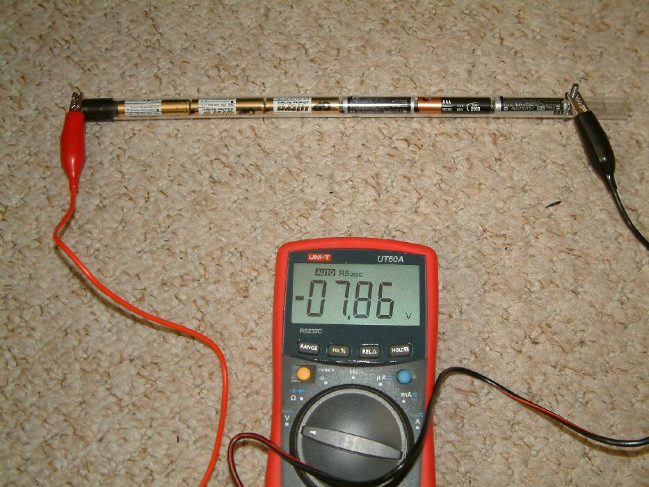
In the next picture we see that two old batteries are in series and this could represent the situation where we have the IR drop caused by the CP system included in the measuring circuit. We can no longer calculate the value of the first old battery as we don't know the value of the second. (The IR drop in the soil is totally dependant on the position of the reference potential)
The next picture shows the effect of a third unknown variable such as the presence of a bi-metalic coupling in the back-fill of a pipeline.
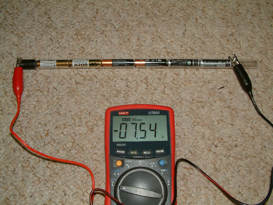
A fourth battery representing another variable such as 'teluric or sunspot effects, is added to the measuring circuit, making it impossible to calculate the voltage of the first old battery we put in the tube. This first old battery can be regarded as the corrosion reaction that we are investigating.
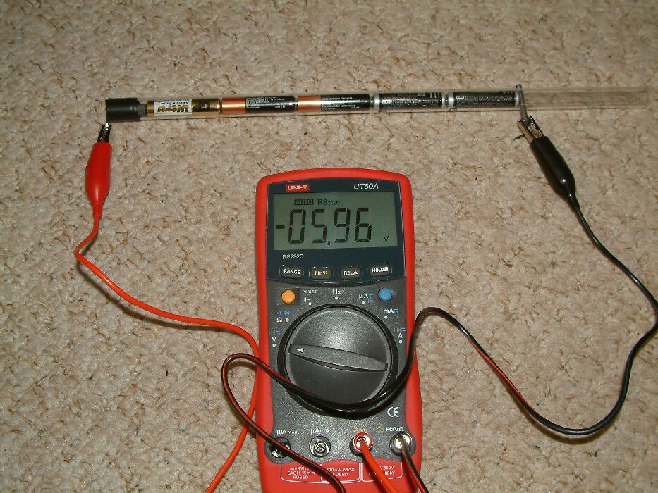
In this next picture we have a single new battery and four old batteries, each of unknown voltage. We need to know the voltage of the first old battery that was put in the tube. The new battery that has been removed can be regarded as the IR drop in the soil which is theoretically removed in the CIPS 'off reading'. The old battery that has been left in can be likened to 'interference currents from other CP systems.
It can be seen that we cannot calculate any individual battery voltage from the data gathered in this measuring circuit.
This is an identical measuring circuit to that used in the CIPS survey.
We therefore cannot gather data suitable to be used in the calculation of cathodic protection design or monitoring.
There is another solution to this problem which is not apparent until we define the problem properly. All we really want to know is if the cathodic protection has stopped corrosion.
The amount of metal going into solution is proportional to the amount of current flowing from the reaction. If the current stops, the corrosion has stopped.
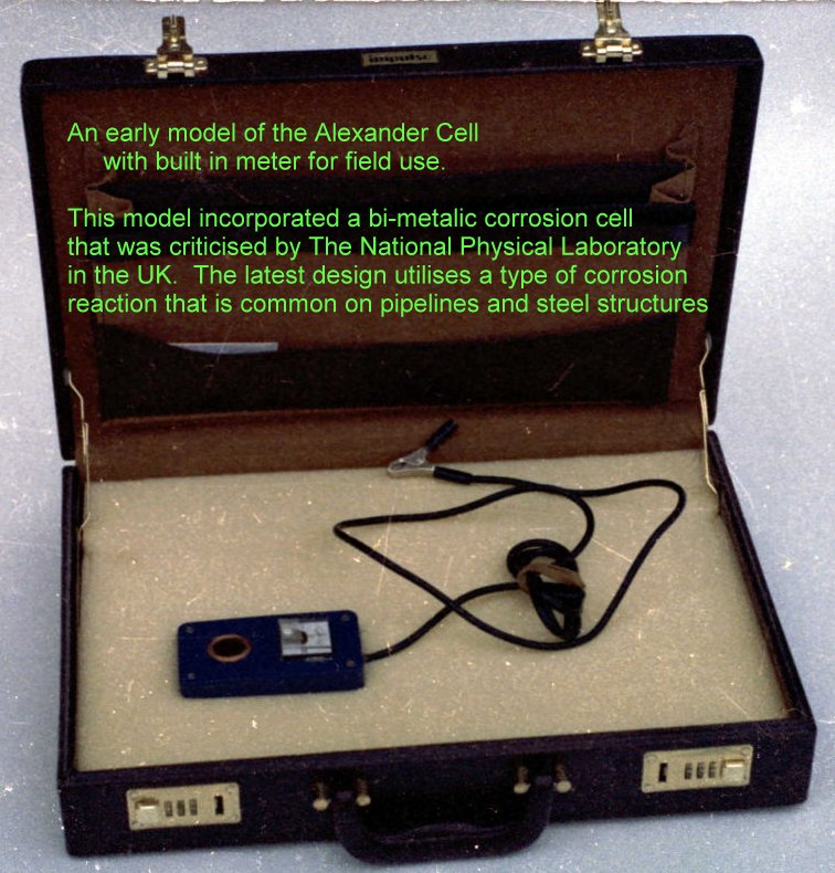
Scientists have now concluded that the only way to measure the corrosion current is with an arrangement of electrodes. Exactly the same arrangement as the Alexander Cell which was demonstrated to the Institute of Corrosion Science and Technology in London in the early 1980's