
Cathodic Protection Network International Limited
Pipeline Corrosion Control
Registered at Companies House in the UK
Name & Registered Office:
CATHODIC PROTECTION NETWORK INTERNATIONAL LIMITED
74 DALCROSS
BRACKNELL
BERKSHIRE
RG12 0UL
Company No. 08505715
Cathodic Protection Network Laboratory 3
This is the third in the series examining the actual measuring of corrosion and the effects of cathodic protection.
In this series we use a copper/copper-sulphate electrode made of a plastic tube (the shell of a ball point pen) filled with copper-sulphate solution and a copper wire to connect to the probe of the meter.
The probe of this electrode is a wooden tooth pick that has a 'capillary action' because of the straight grain and strength of the wood..
This serves the same purpose as a 'luggin capillary' to contact the electrolyte in which the subject metal us immersed.
set up
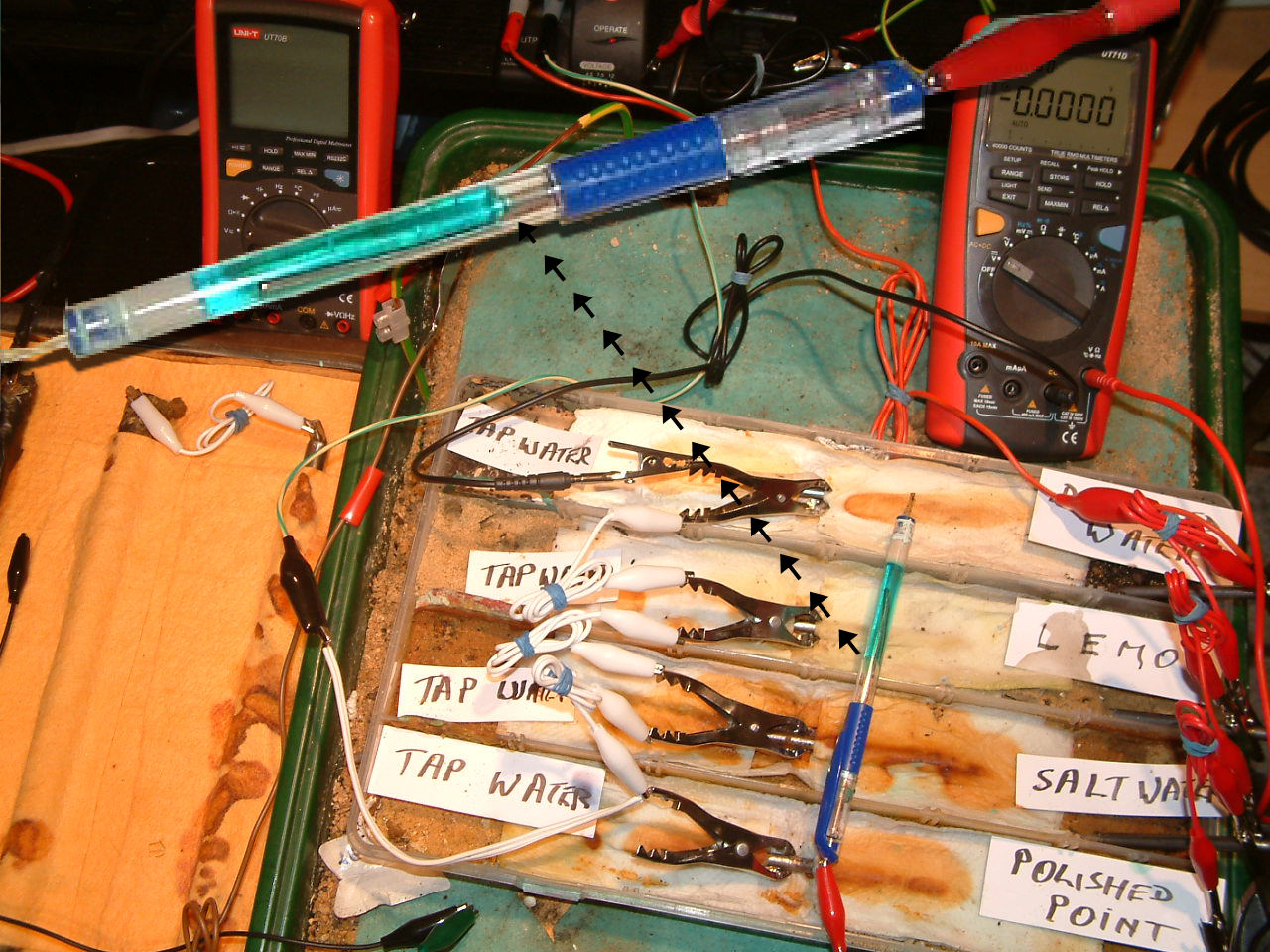
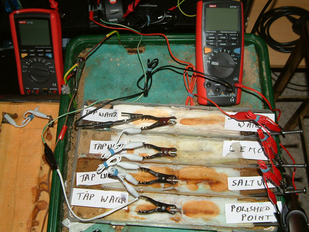
The picture below shows how the four nails are wired so that they are subject to impressed current cathodic protection. The white wires bond all the nails to the green wire that goes to the negative of the TR. The red wires bond all of the additional nails, that are the impressed current anodes, discharging current from the positive of the TR into the electrolyte.
set up 2
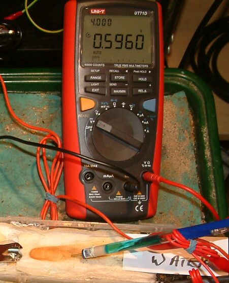
Pipe-to-soil 1
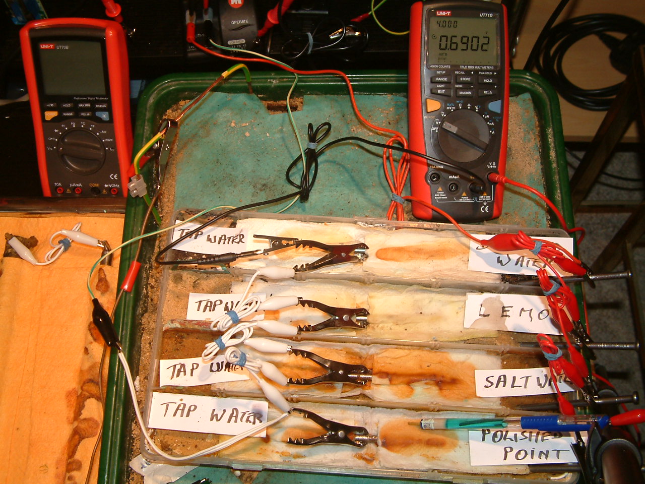
The meter is switched on to volts and the common is connected to the subject nails that are bonded together with the white wires to the green wire from the negative of the DC power supply. The current is being drained from the subject nails in the centre positions and the electrolyte is being charged to 0.6902 volts with reference to the copper/coppr-sulphate electrode placed in the first partition.
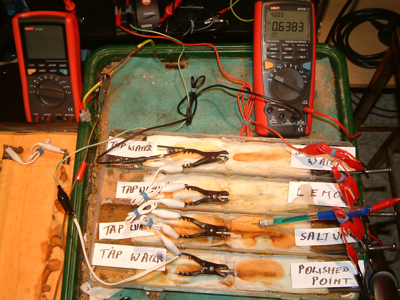
pipe-to-soil 2
The 'half-cell' is placed in the second partition and the reading is 0.6383 volts. This means that the electrolyte at this point has a potential higher than the subject nails to the value of 0.6383 minus the value of the copper/copper-sulphate reaction potential. (around 0.320v).

pipe-to-soil 3
The ground contact electrode is placed in the third partition and the meter displays 0.5379 volts. Observe that this is the potential difference between the nails connacted to the negative pole of the transformer rectifier and the tip of the half cell in the electrolyte that has been soaked in lemon juice in the third partition.
pipe-to-soil 4
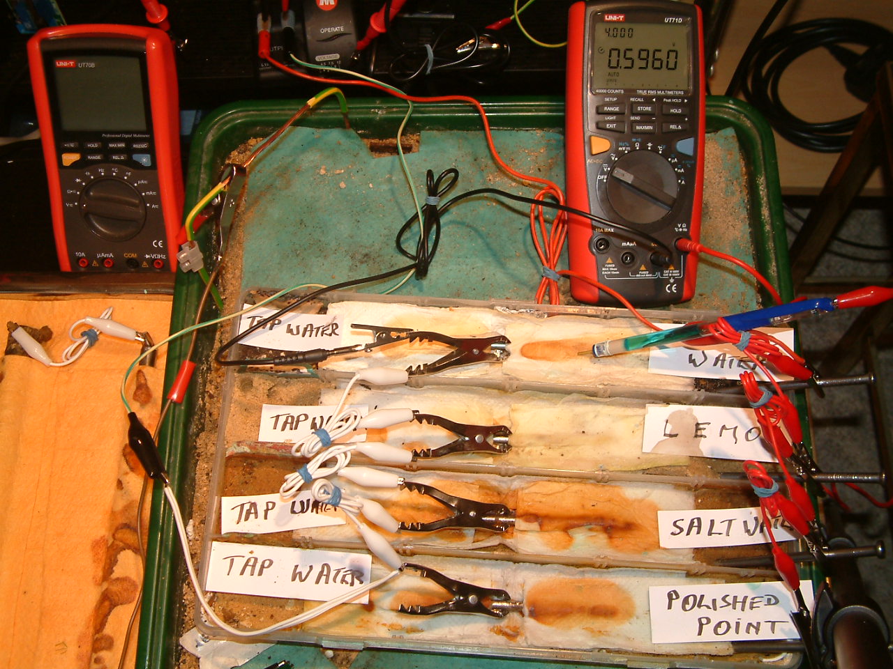
The ground contact electrode is placed in the forth partition and the meter displays 0.5960 volts.
At this point it is time to consider the similarity and differences between this demonstration and actual pipe-to-soil potential measurements as practiced in cathodic protection field work.
Visualise that the subject nails are coating faults along an old pipeline to which we have just installed cathodic protection.
All of the coating faults are connected by the pipeline metal that has very low resistance, so the white wires are similar to the electrical qualities of the pipeline.
The anode nails, however, cannot represent the anodes in an impressed current system in the field as they are too close to the subject metal.
This closeness and the insulated trough in which the are placed makes the current too directional and not as experienced in piepeline cathodic protection in the field.
pipe-to-soil 5
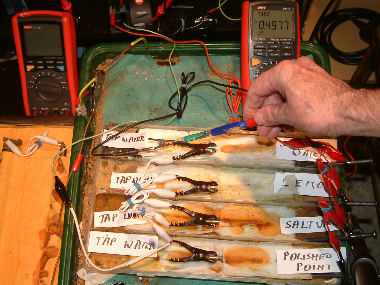
The Luggin capillary probe is placed under the nail crocadile clip in the fourth partition, in contact with the electrolyte at this point. The electrolyte potential at this location is seen to be 0.4977 v more than the subject nails that the meter sees as zero. Of course we have to subtract the copper/copper-sulphate reaction potential that is in series with this measurement.
pipe-to-soil 6
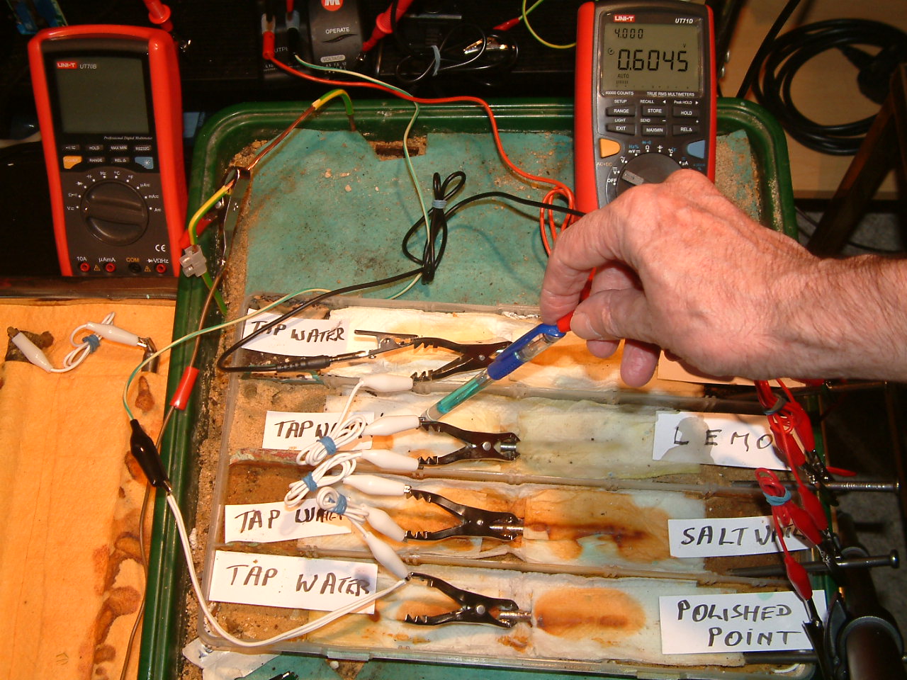
The Luggin capillary probe is placed under the nail crocadile clip in the third partition, in contact with the electrolyte at this point. The electrolyte potential at this location is seen to be 0.6045 v more than the subject nails that the meter sees as zero.
pipe-to-soil 7
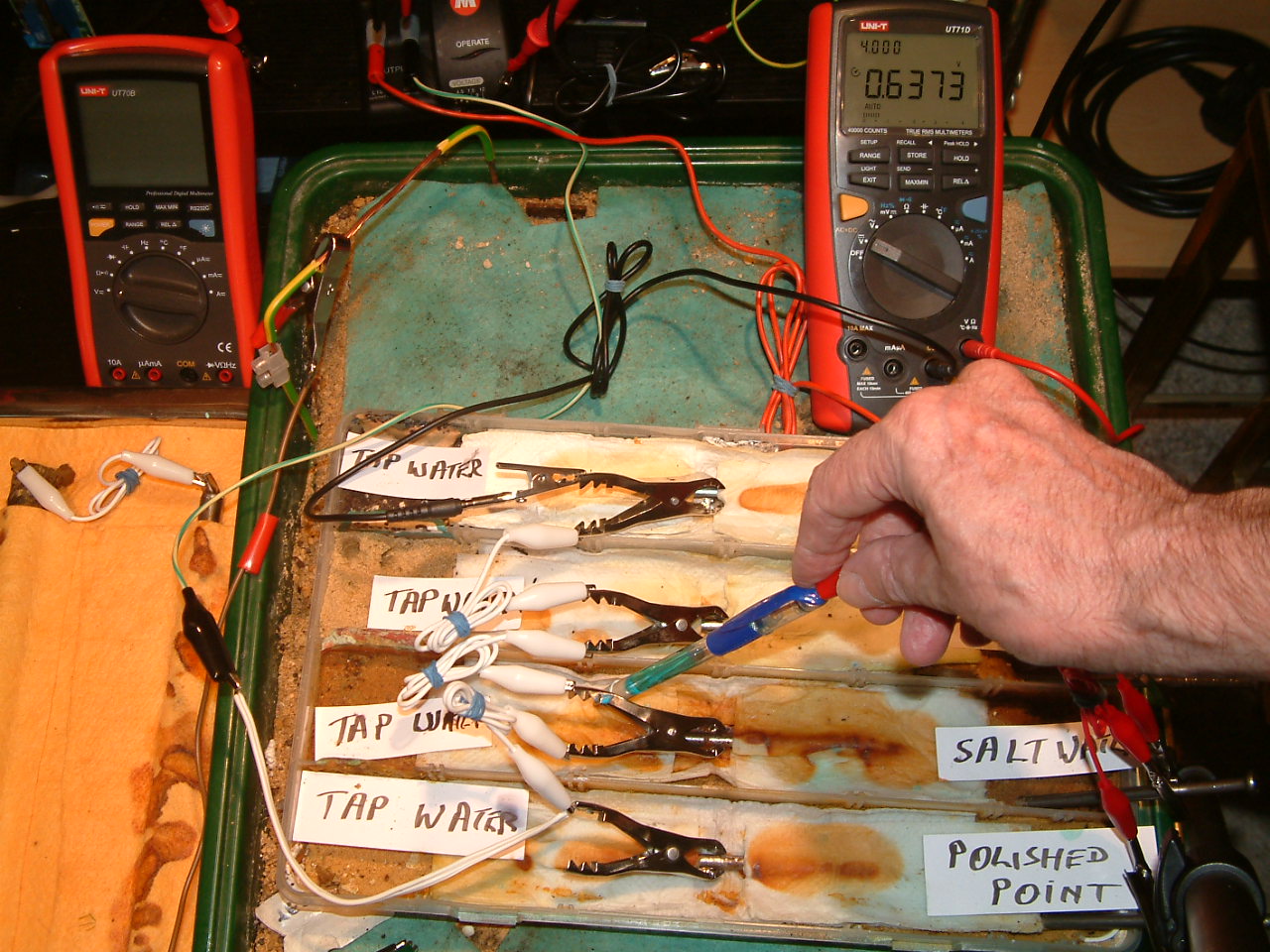
The copper/copper-sulphate capillary probe is placed under the nail crocodile clip in the second partition, in contact with the electrolyte at this point. The electrolyte potential at this location is seen to be 0.6373 v more than the subject nails that the meter sees as zero.
pipe-to-soil 8
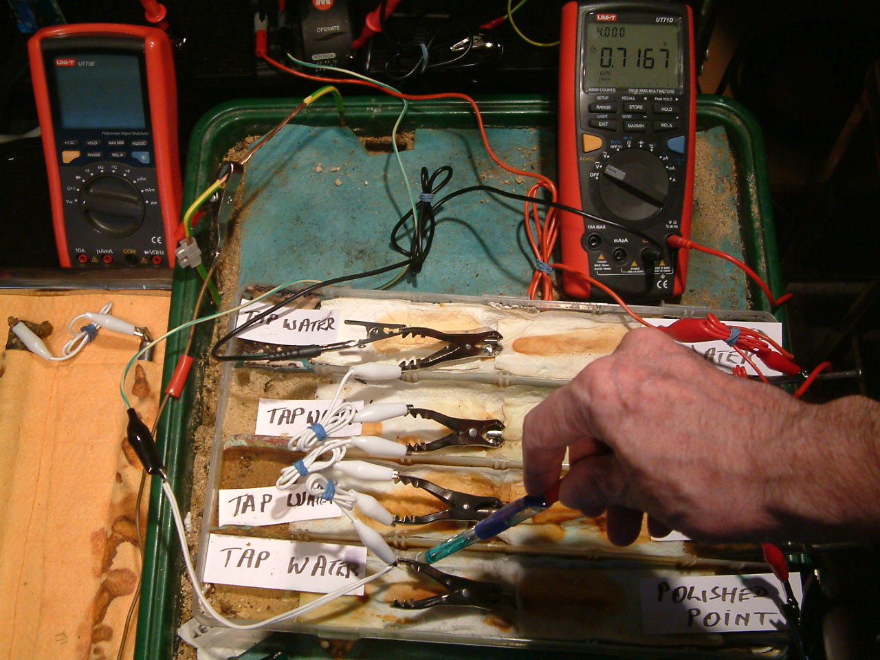
The copper/copper-sulphate electrode probe is placed under the nail crocodile clip in the first partition, in contact with the electrolyte at this point. The electrolyte potential at this location is seen to be 0.7167 v more than the subject nails that the meter sees as zero.
pipe-to-soil 9
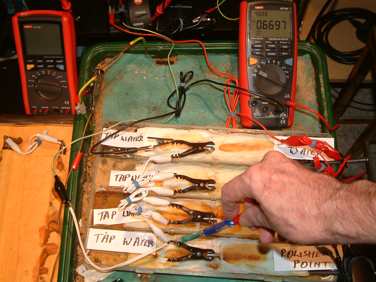
The copper/copper-sulphate electrode probe remains under the nail crocodile clip in the first partition, in contact with the electrolyte at this point. The electrolyte potential at this location has changed to 0.6697 v more than the subject nails that the meter sees as zero.
pipe-to-soil 10
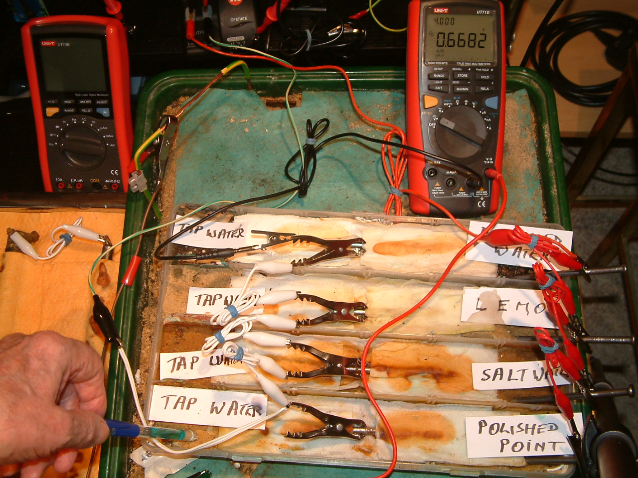
The copper/copper-sulphate electrode probe is moved to a new position in the first partition. The electrolyte potential at this location is 0.6682 v more than the subject nails that the meter sees as zero.
pipe-to-soil 11
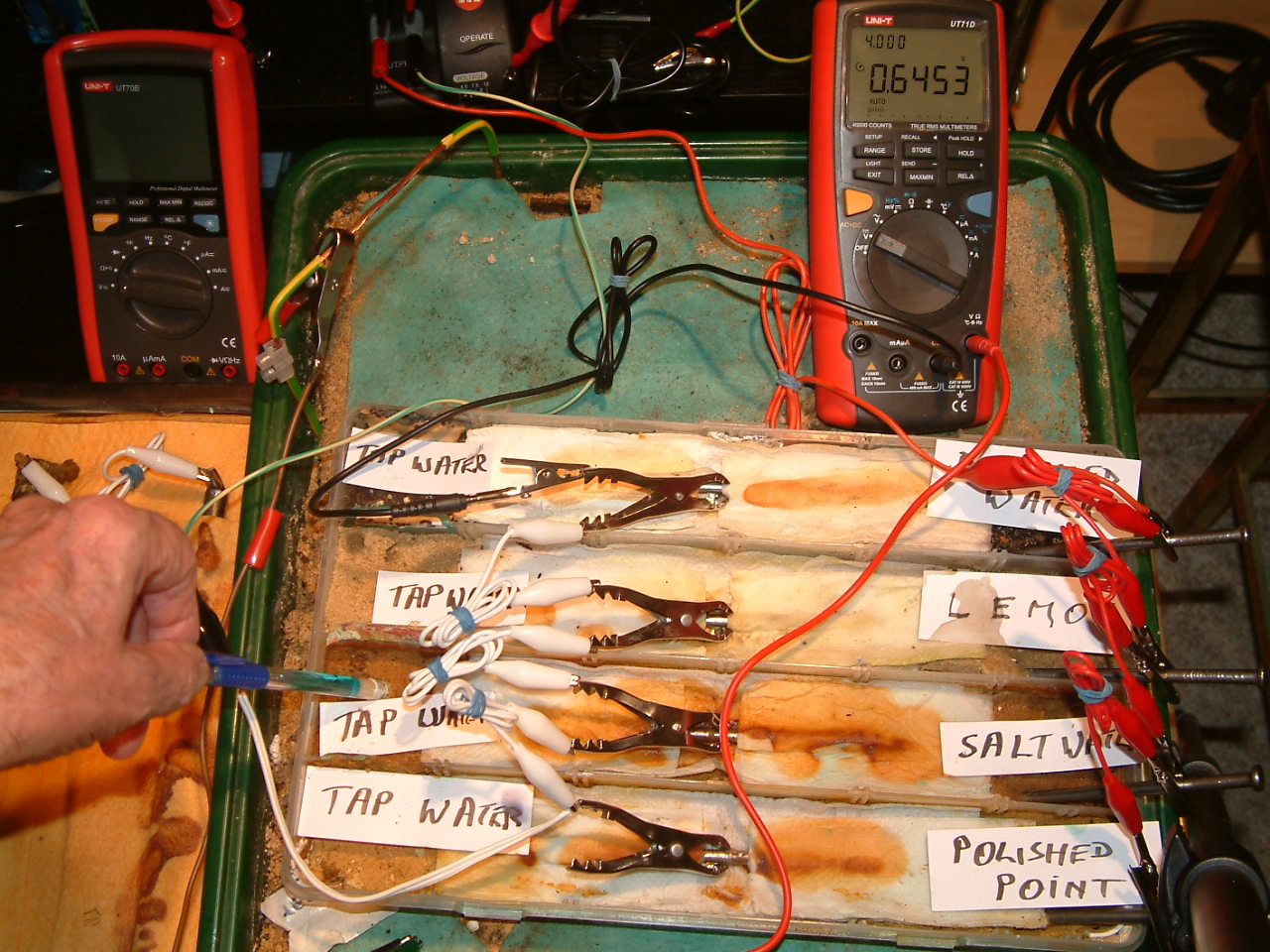
The copper/copper-sulphate electrode probe is moved to a position in the second partition. The electrolyte potential at this location is 0.6453 v more than the subject nails that the meter sees as zero.
pipe-to-soil 12
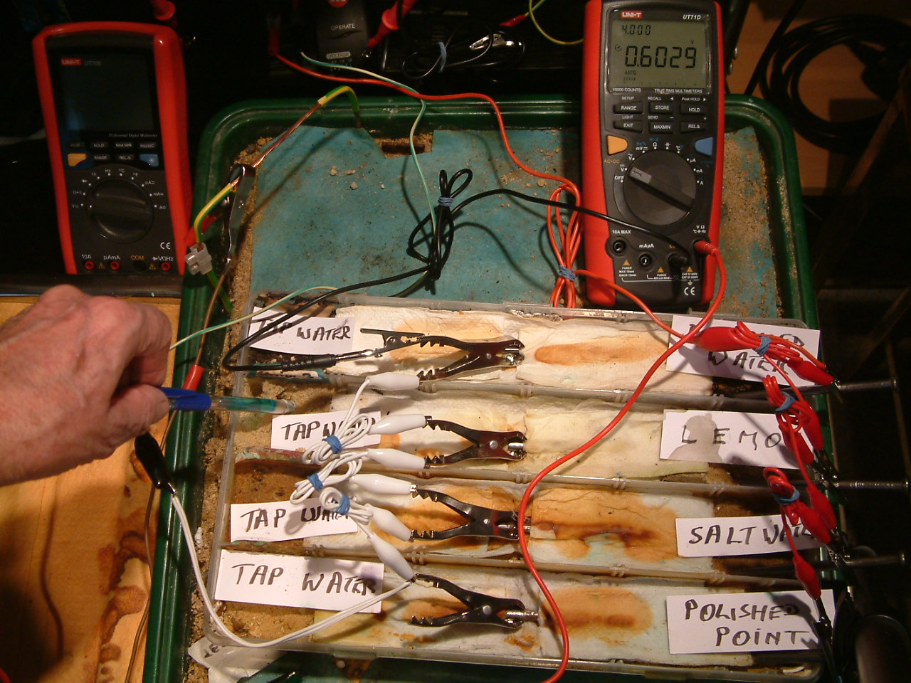
The copper/copper-sulphate electrode probe is moved to a position in the third partition. The electrolyte potential at this location is 0.6029 v more than the subject nails that the meter sees as zero.
pipe-to-soil 13
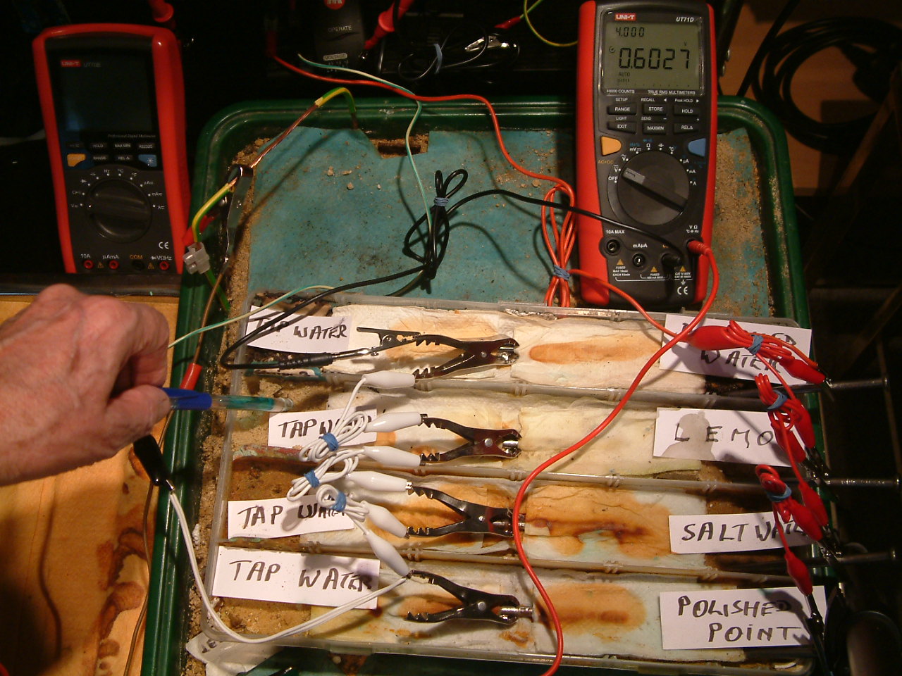
The copper/copper-sulphate electrode probe remains in the same position in the third partition. The electrolyte potential at this location is 0.6027 v more than the subject nails that the meter sees as zero.
pipe-to-soil 14
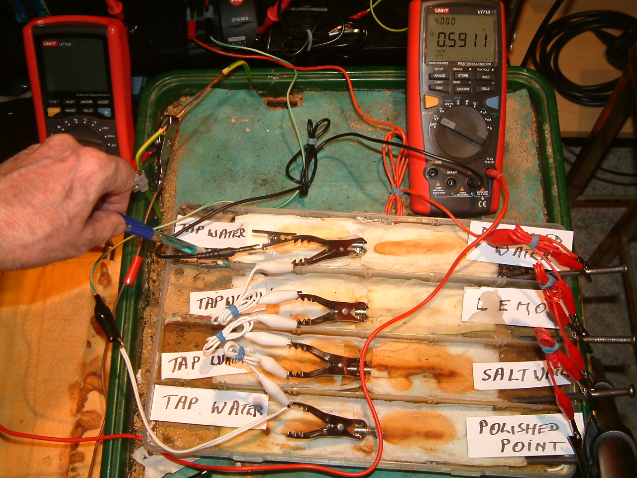
The copper/copper-sulphate electrode probe is moved to the fourth partition. The electrolyte potential at this location is 0.5911 v more than the subject nails that the meter sees as zero.
pipe-to-soil 15
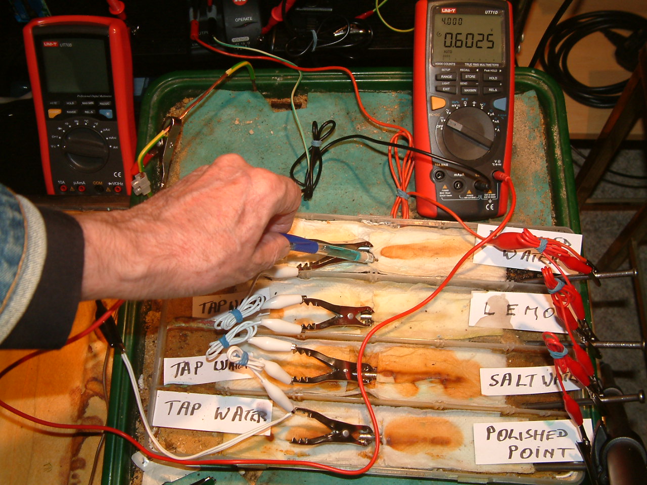
The copper/copper-sulphate electrode probe is moved to a new position in the fourth partition. The electrolyte potential at this location is 0.6025 v more than the subject nails that the meter sees as zero.
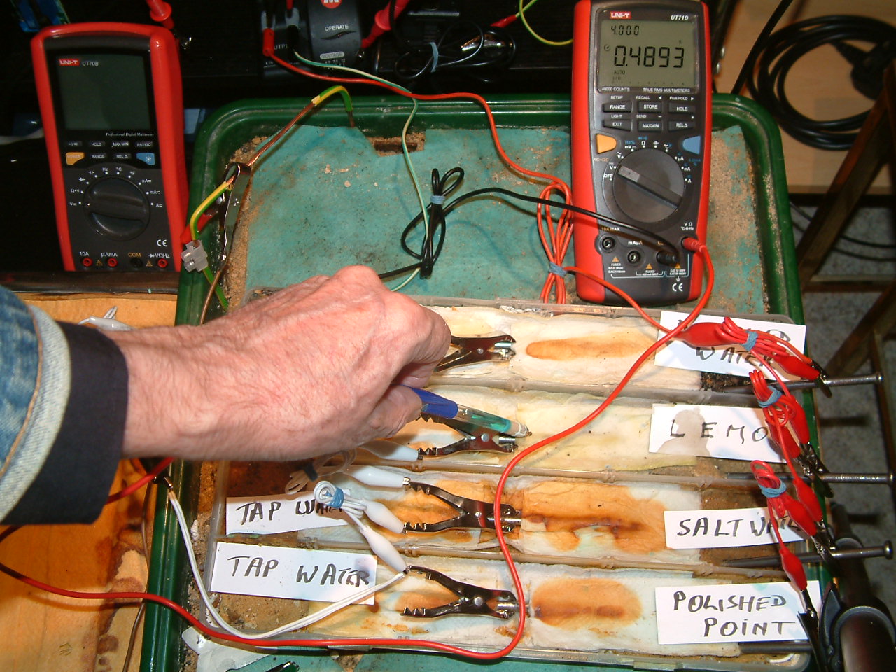
pipe-to-soil 16
The copper/copper-sulphate electrode probe is moved to a position in the third partition. The electrolyte potential at this location is 0.4893 v more than the subject nails that the meter sees as zero.
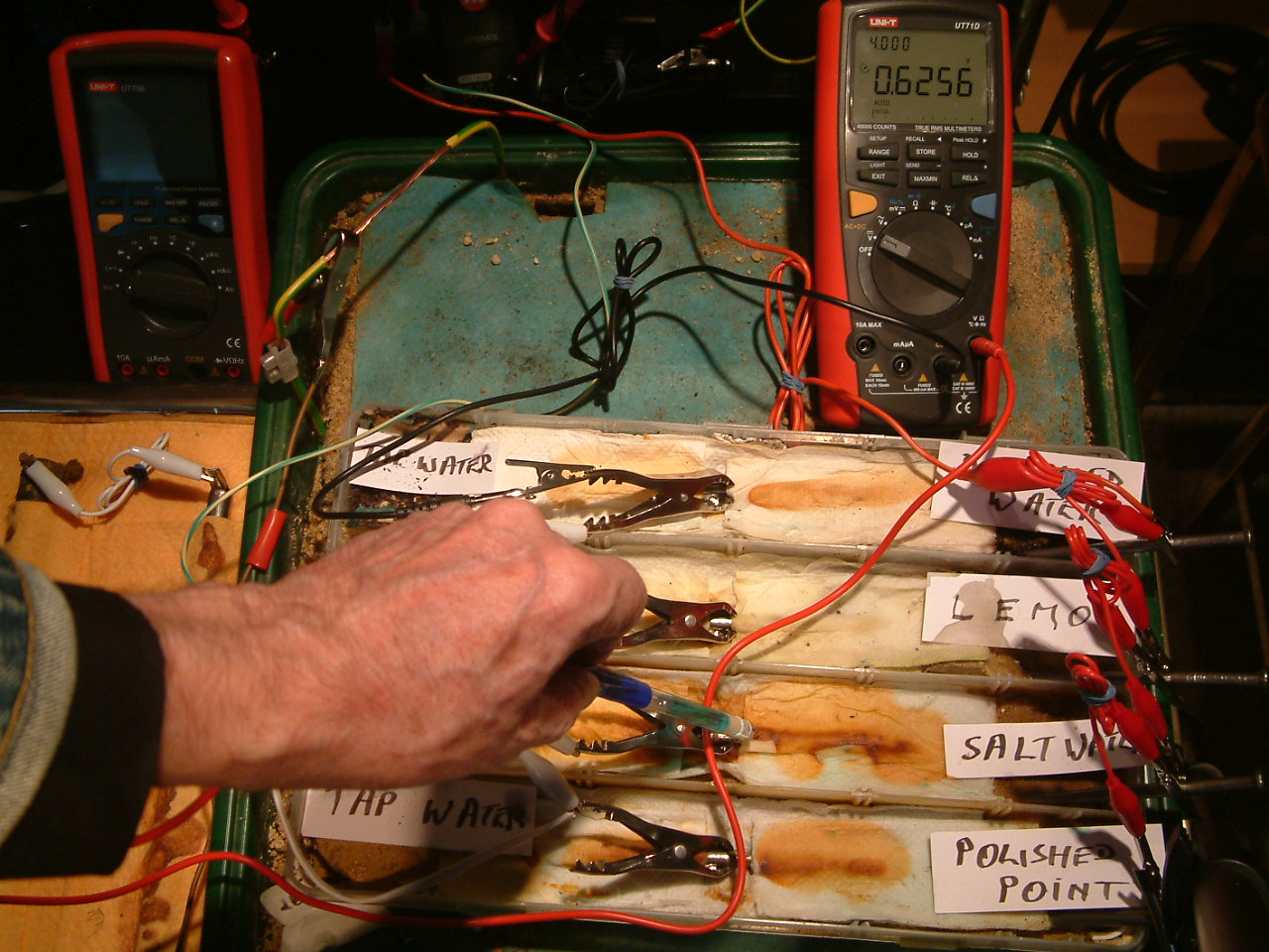
pipe-to-soil 17
The copper/copper-sulphate electrode probe is moved to a position in the second partition. The electrolyte potential at this location is 0.6256 v more than the subject nails that the meter sees as zero.
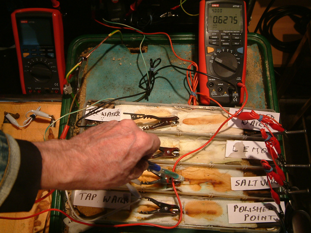
pipe-to-soil 18
The copper/copper-sulphate electrode probe remains in the same position in the second partition. The electrolyte potential at this location is has changed to 0.6275 v more than the subject nails that the meter sees as zero.
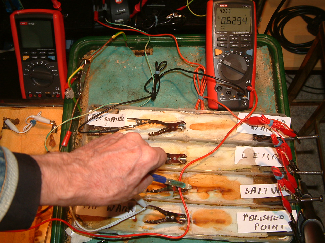
pipe-to-soil 19
The copper/copper-sulphate electrode probe remains in the same position in the second partition. The electrolyte potential at this location is has changed to 0.6294 v more than the subject nails that the meter sees as zero. These are potential changes over time in the potential of the electrolyte at the point of contact.
pipe-to-soil 20
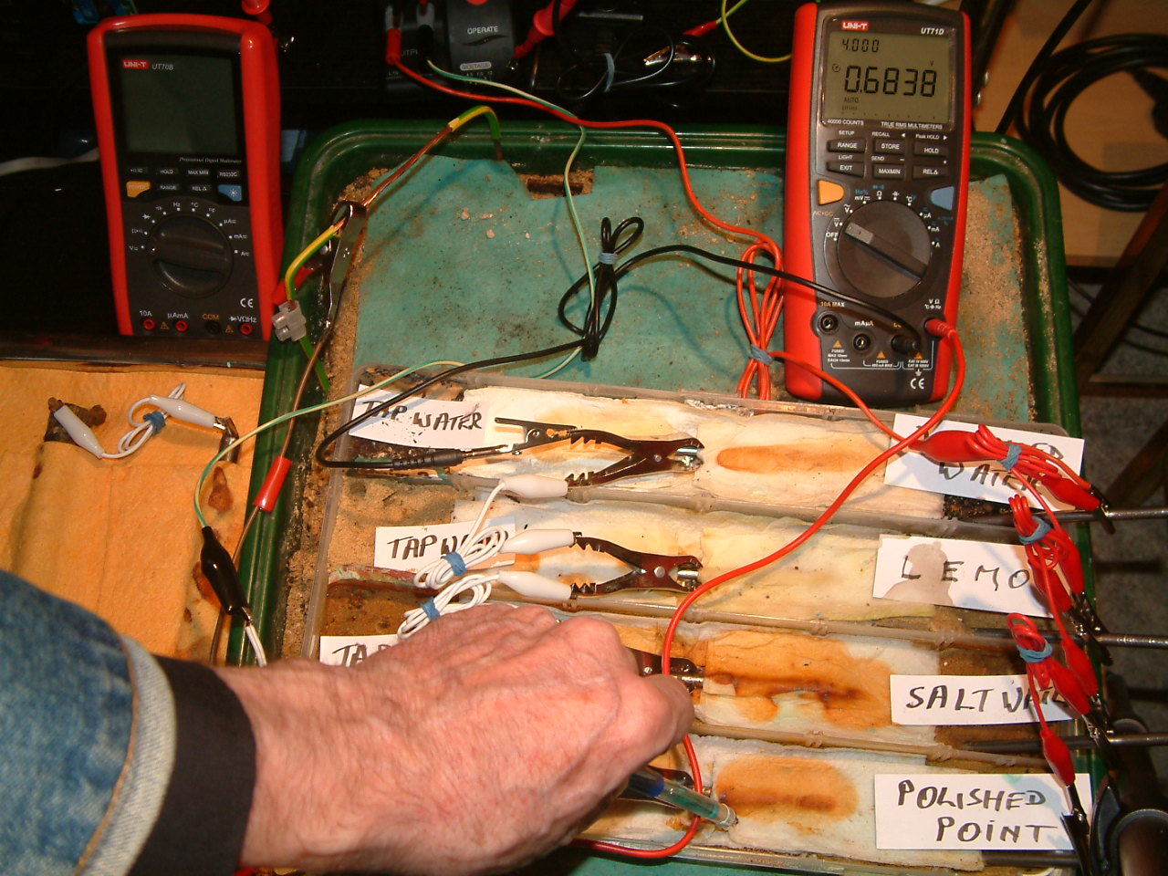
The copper/copper-sulphate electrode probe is move to a new position in the first partition. The electrolyte potential at this location is has changed to 0.6838 v more than the subject nails that the meter sees as zero.
>
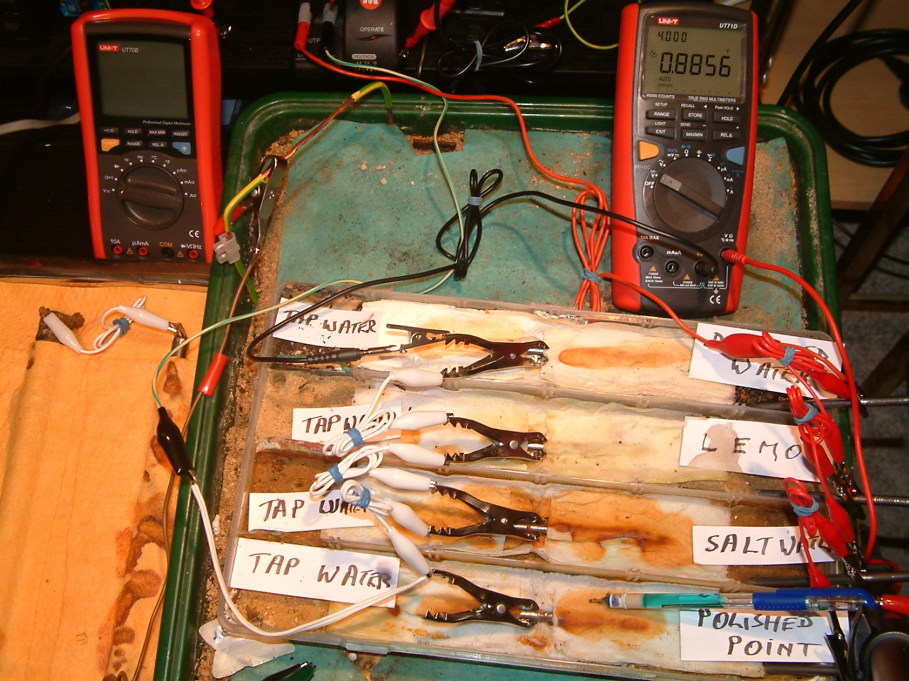
pipe-to-soil 21
You can now see that the power supply has been energised as the red light is on, to the right of the DC output terminals. The voltage between the copper/copper-sulphate electrode in partition one is now 0.8856v.
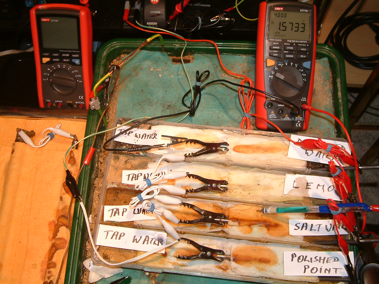
pipe-to-soil 22
The power supply is energised and the potential difference between the copper/copper-sulphate electrode in partition two and the subject nails is now 1.5733 v.
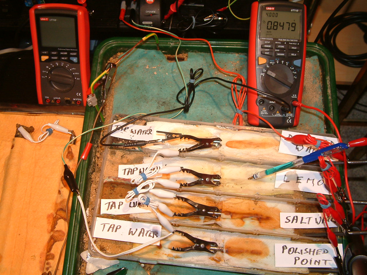
pipe-to-soil 23
The power supply is energised and the potential difference between the copper/copper-sulphate electrode in partition three and the subject nails is now 0.8479 v.
pipe-to-soil 24
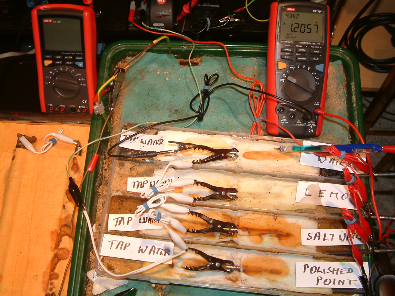
The power supply is energised and the potential difference between the copper/copper-sulphate electrode in partition four and the subject nails is now 1.2057v.
pipe-to-soil 25
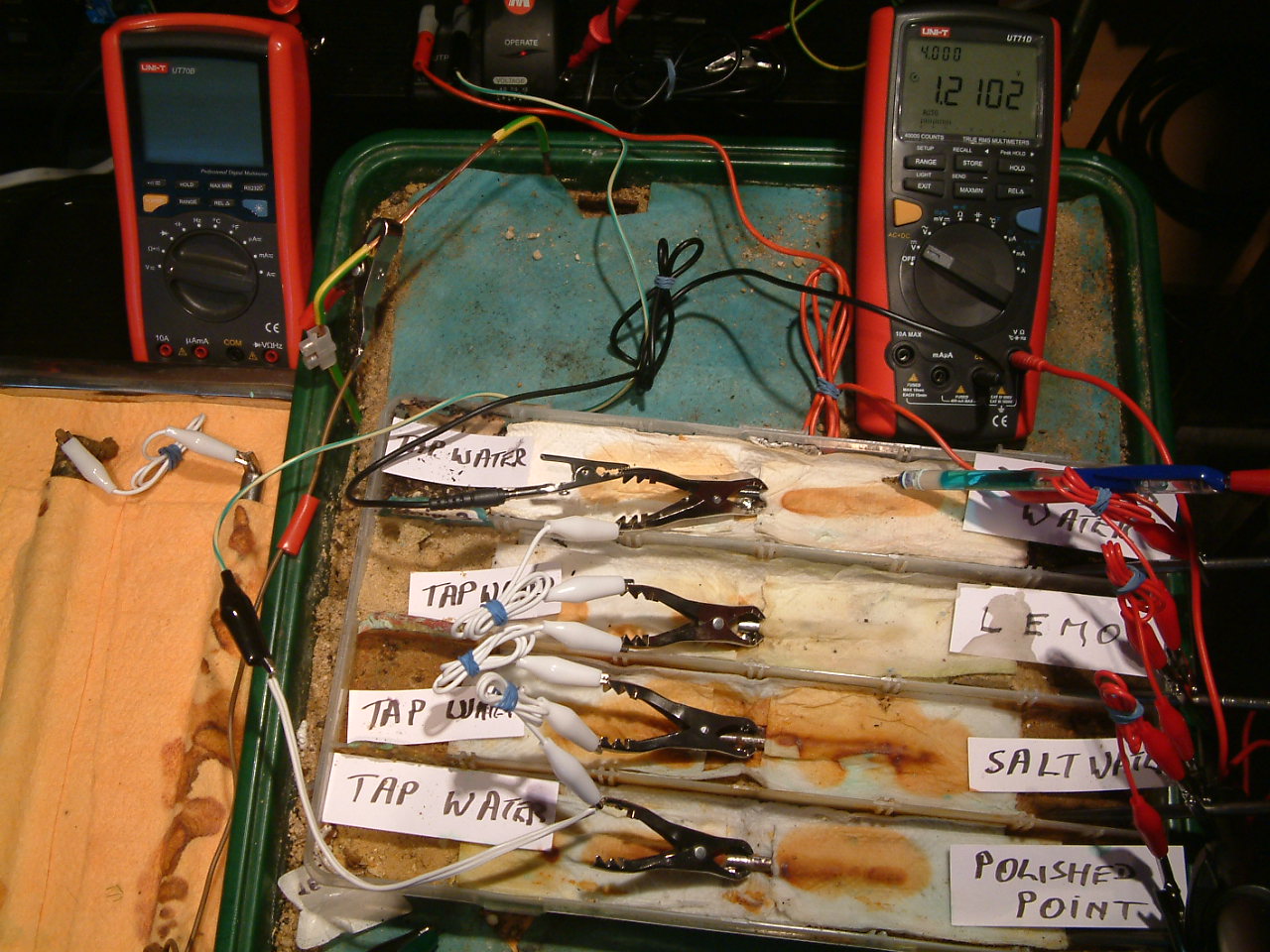
The power supply is energised and the potential difference between the copper/copper-sulphate electrode in partition four and the subject nails is now 1.2102v.
pipe-to-soil 26
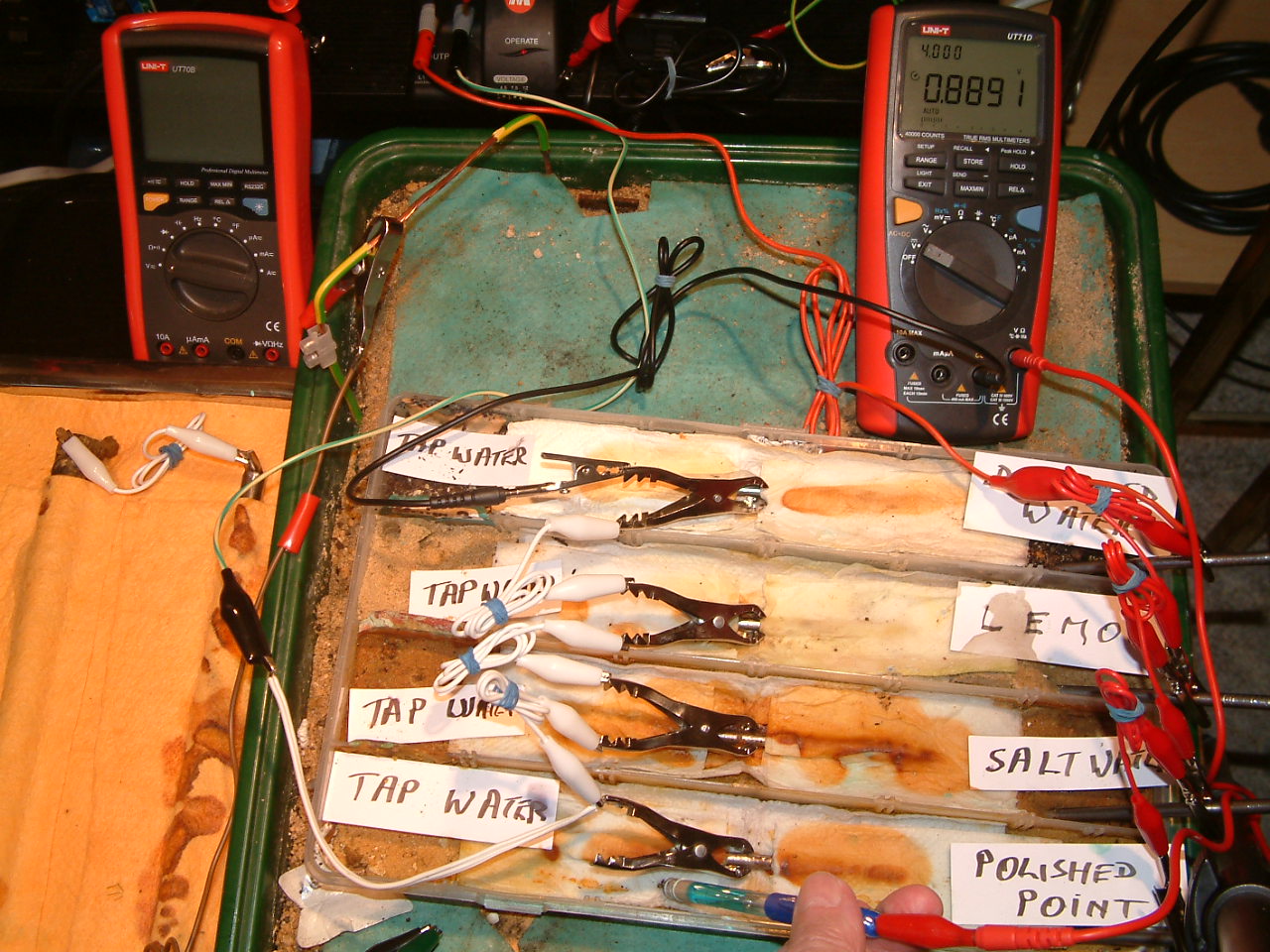
The power supply is energised and the potential difference between the copper/copper-sulphate electrode in partition one and the subject nails is now 0.8891v. It is noted that the Luggin probe is in a different position in partition one.
pipe-to-soil 27
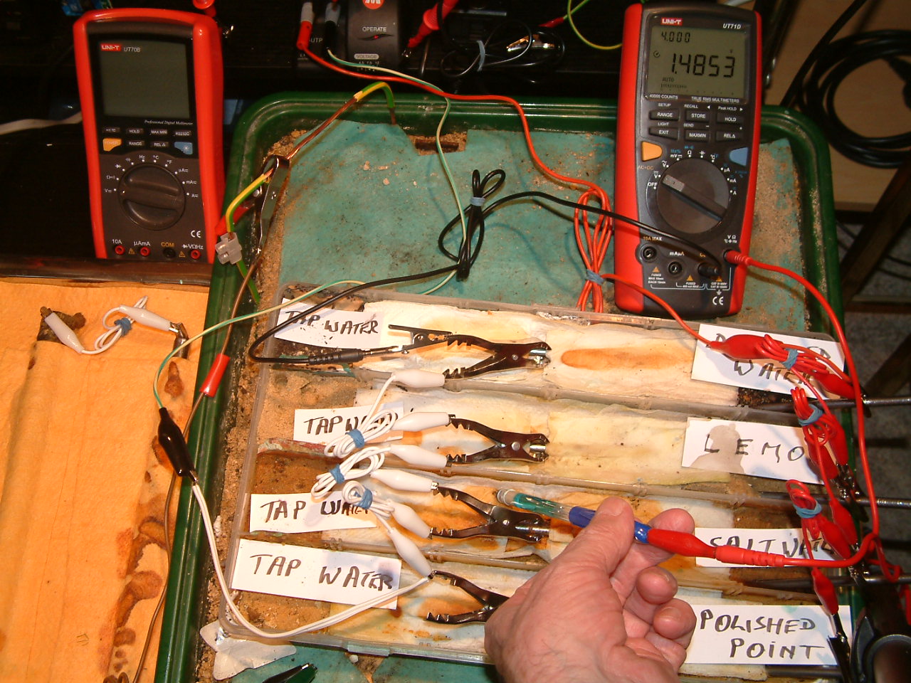
The power supply is energised and the potential difference between the copper/copper-sulphate electrode in partition two and the subject nails is now 1.4853v. It is noted that the Luggin probe is in a different position in partition two.
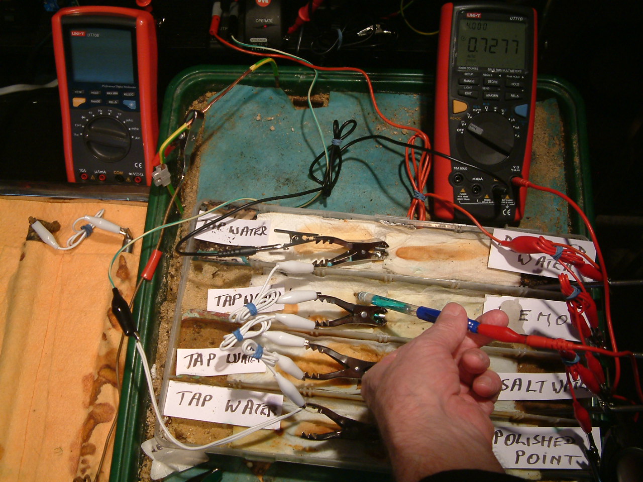
pipe-to-soil 28
The power supply is energised and the potential difference between the copper/copper-sulphate electrode in partition three and the subject nails is now 0.7277v. It is noted that the Luggin probe is in a different position in partition three.
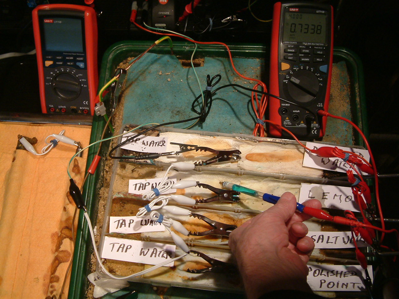
pipe-to-soil 29
The power supply is energised and the potential difference between the copper/copper-sulphate electrode in partition three and the subject nails is now 0.7338v. It is noted that the Luggin probe is in a different position in partition three.
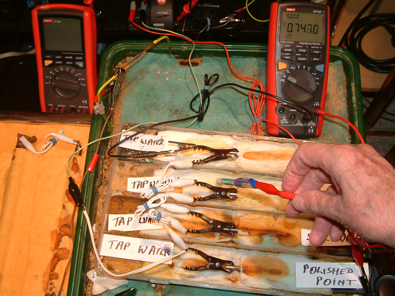
pipe-to-soil 30
The power supply is energised and the potential difference between the copper/copper-sulphate electrode in partition three and the subject nails is now 0.7488v. It is noted that the Luggin probe is in a different position in partition three.
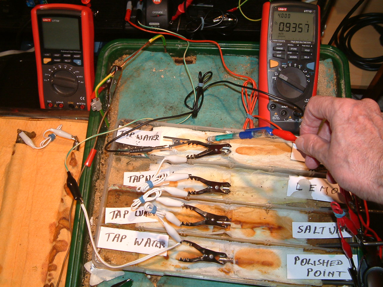
pipe-to-soil 31
The power supply is energised and the potential difference between the copper/copper-sulphate electrode in partition four and the subject nails is now 0.9357v. It is noted that the Luggin probe is in a different position in partition four.
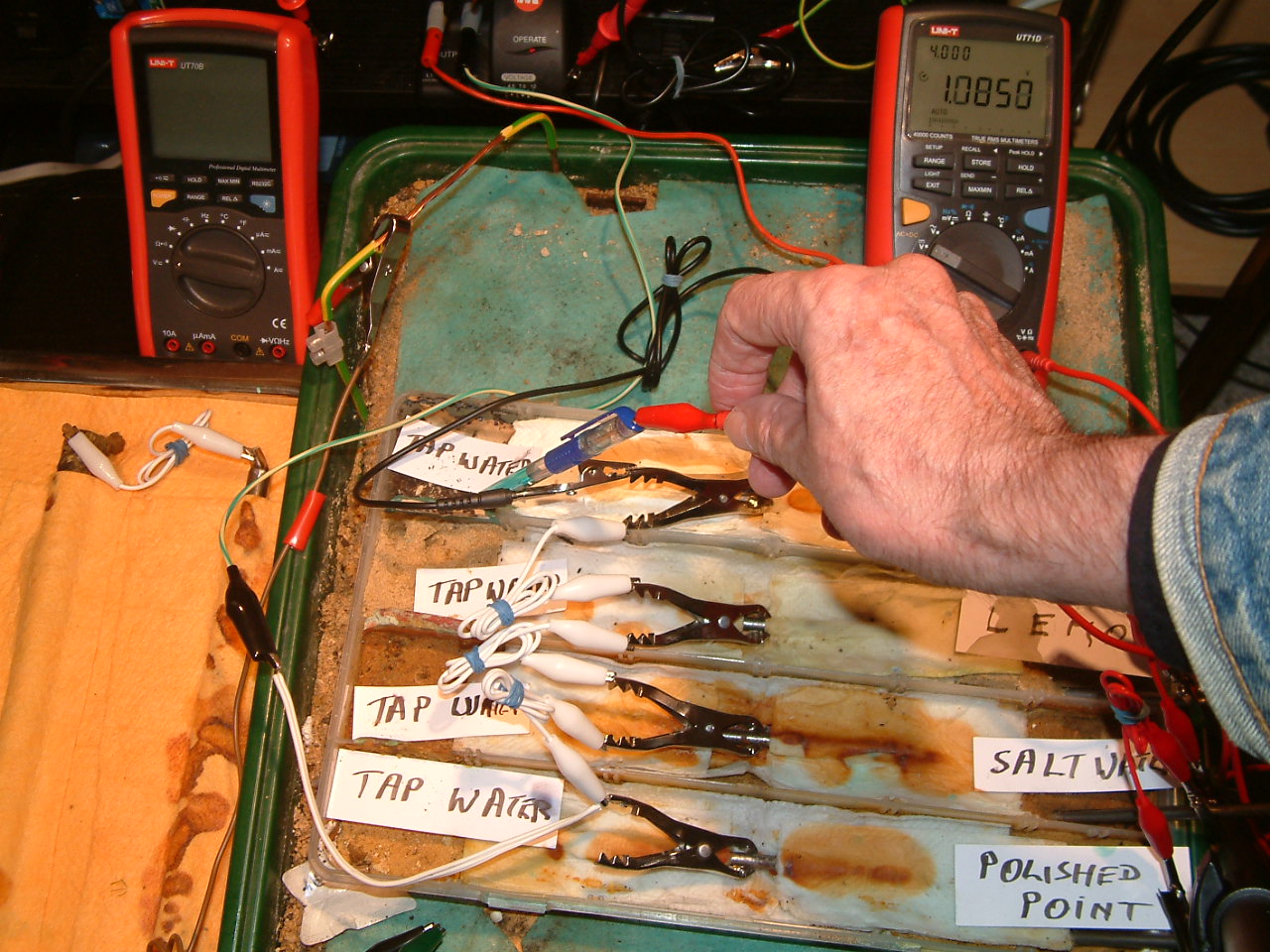
pipe-to-soil 32
The power supply is energised and the potential difference between the copper/copper-sulphate electrode in partition four and the subject nails is now 1.0850v. It is noted that the Luggin probe is in a different position in partition four.
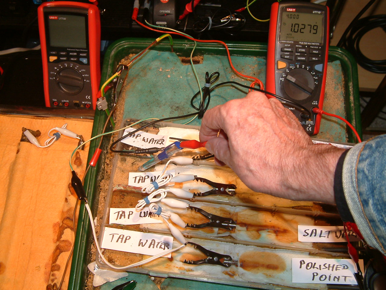
pipe-to-soil 33
The power supply is energised and the potential difference between the copper/copper-sulphate electrode in partition three and the subject nails is now 1.0279v. It is noted that the Luggin probe is in a different position in partition three.
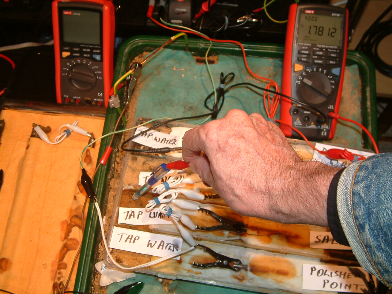
pipe-to-soil 34
The power supply is energised and the potential difference between the copper/copper-sulphate electrode in partition two and the subject nails is now 1.7812v. It is noted that the Luggin probe is in a different position in partition two.
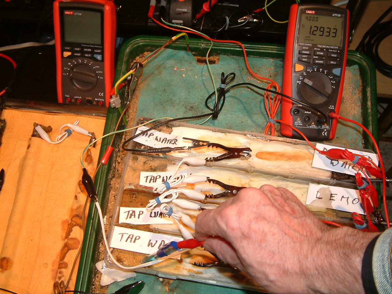
pipe-to-soil 35
The power supply is energised and the potential difference between the copper/copper-sulphate electrode in partition one and the subject nails is now 1.2933v. It is noted that the Luggin probe is in a different position in partition one.
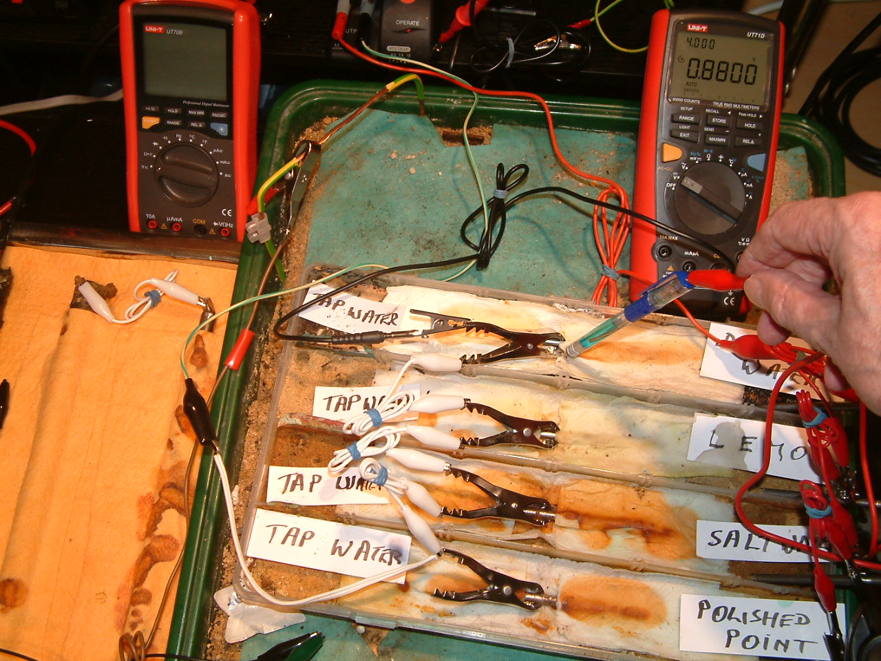
pipe-to-soil 36
The power supply is energised and the potential difference between the copper/copper-sulphate electrode in partition four and the subject nails is now 0.8800v. It is noted that the Luggin probe is in a different position in partition four and is close to the subject nail. On a pipeline this is the equivalent to placing the half-cell close to the pipe in an excavation where there is a coating fault nearby.
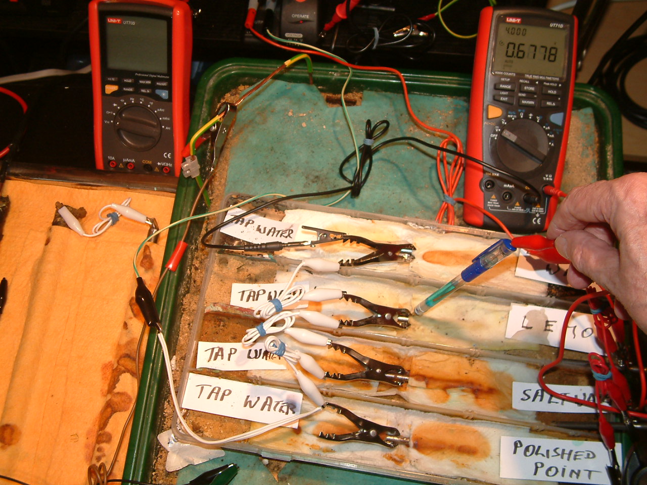
pipe-to-soil 37
The power supply is energised and the potential difference between the copper/copper-sulphate electrode in partition three and the subject nails is now 0.6778v.
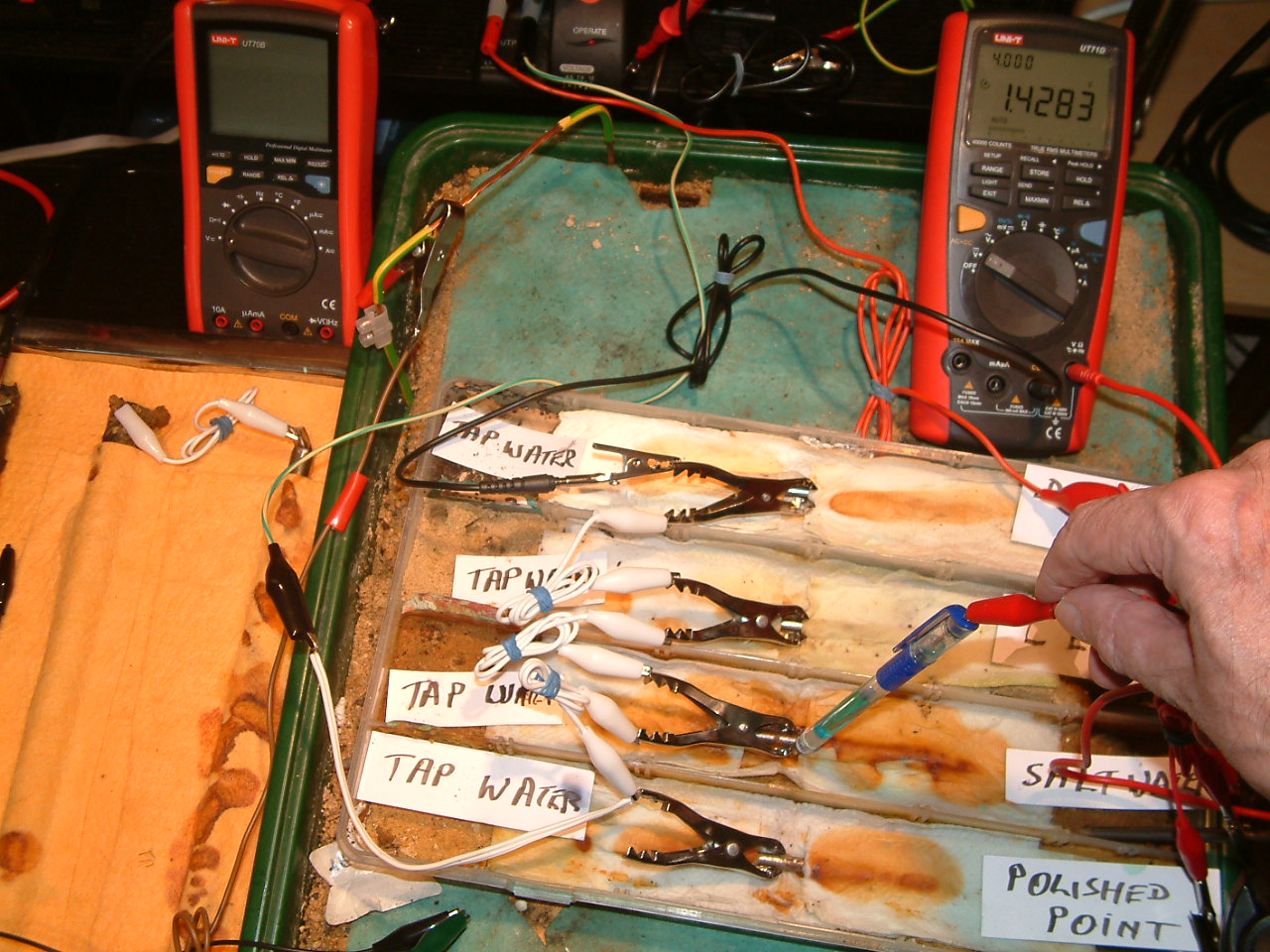
pipe-to-soil 38
The power supply is energised and the potential difference between the copper/copper-sulphate electrode in partition two and the subject nails is now 1.4283v.
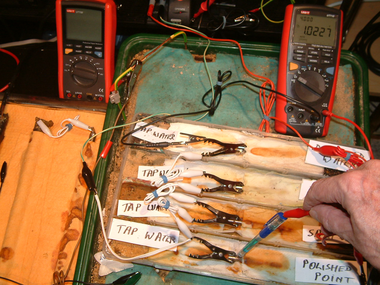
pipe-to-soil 39
The power supply is energised and the potential difference between the copper/copper-sulphate electrode in partition one and the subject nails is now 1.0277v.
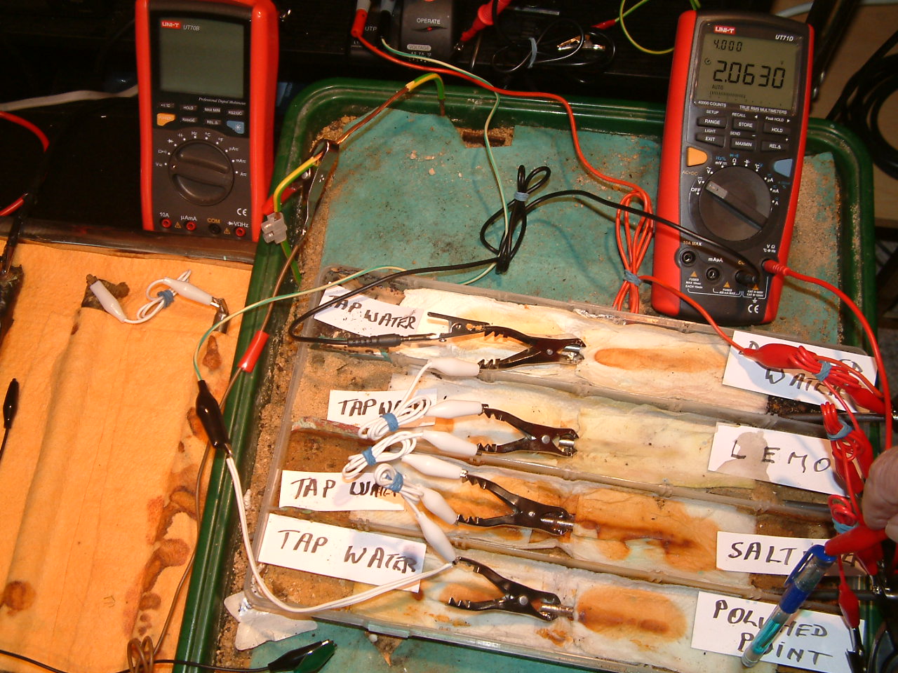
pipe-to-soil 40
The power supply is energised and the potential difference between the copper/copper-sulphate electrode in partition one and the subject nails is now 2.0630v.
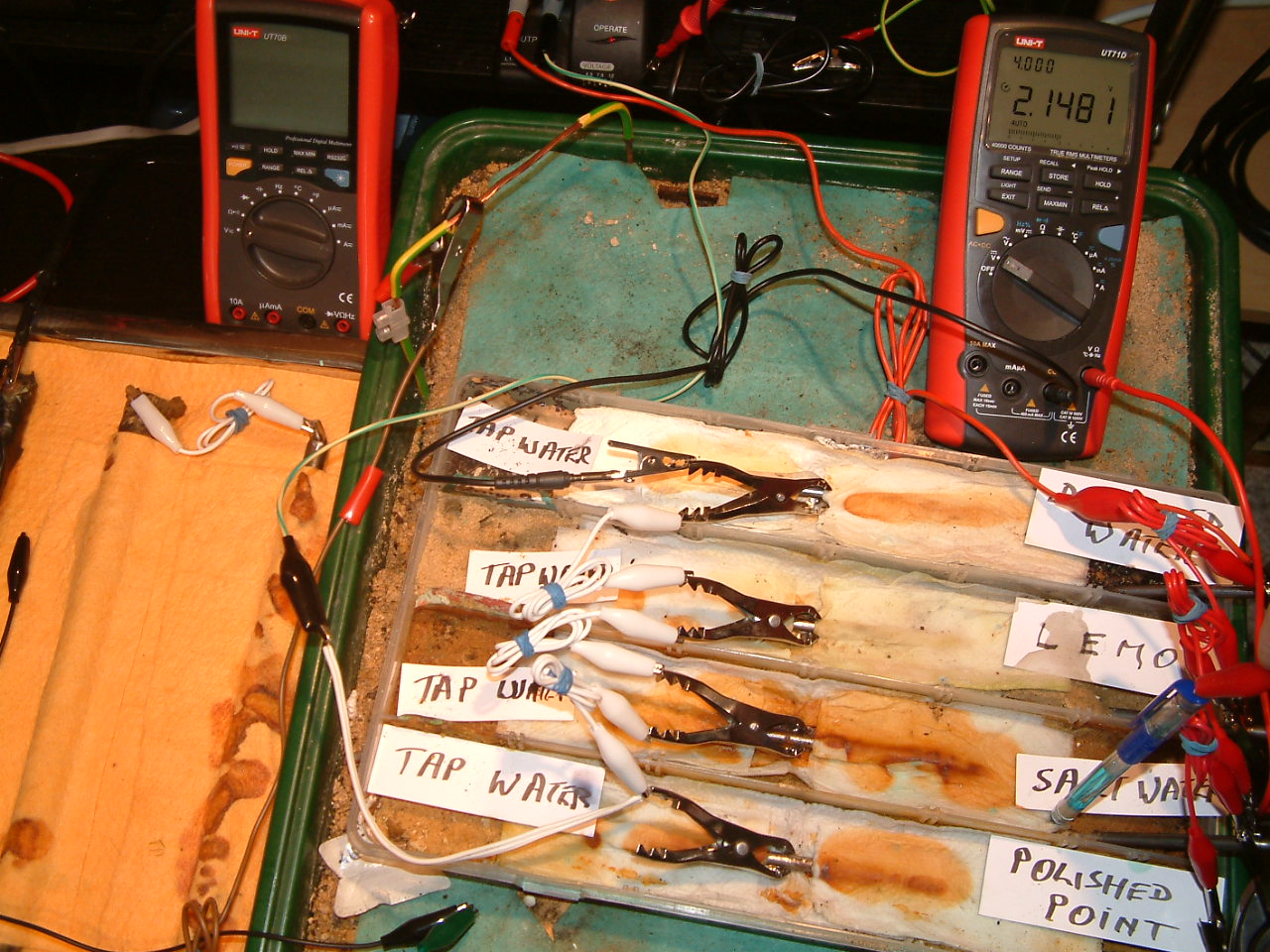
pipe-to-soil 41
The power supply is energised and the potential difference between the copper/copper-sulphate electrode in partition two and the subject nails is now 2.1481v.
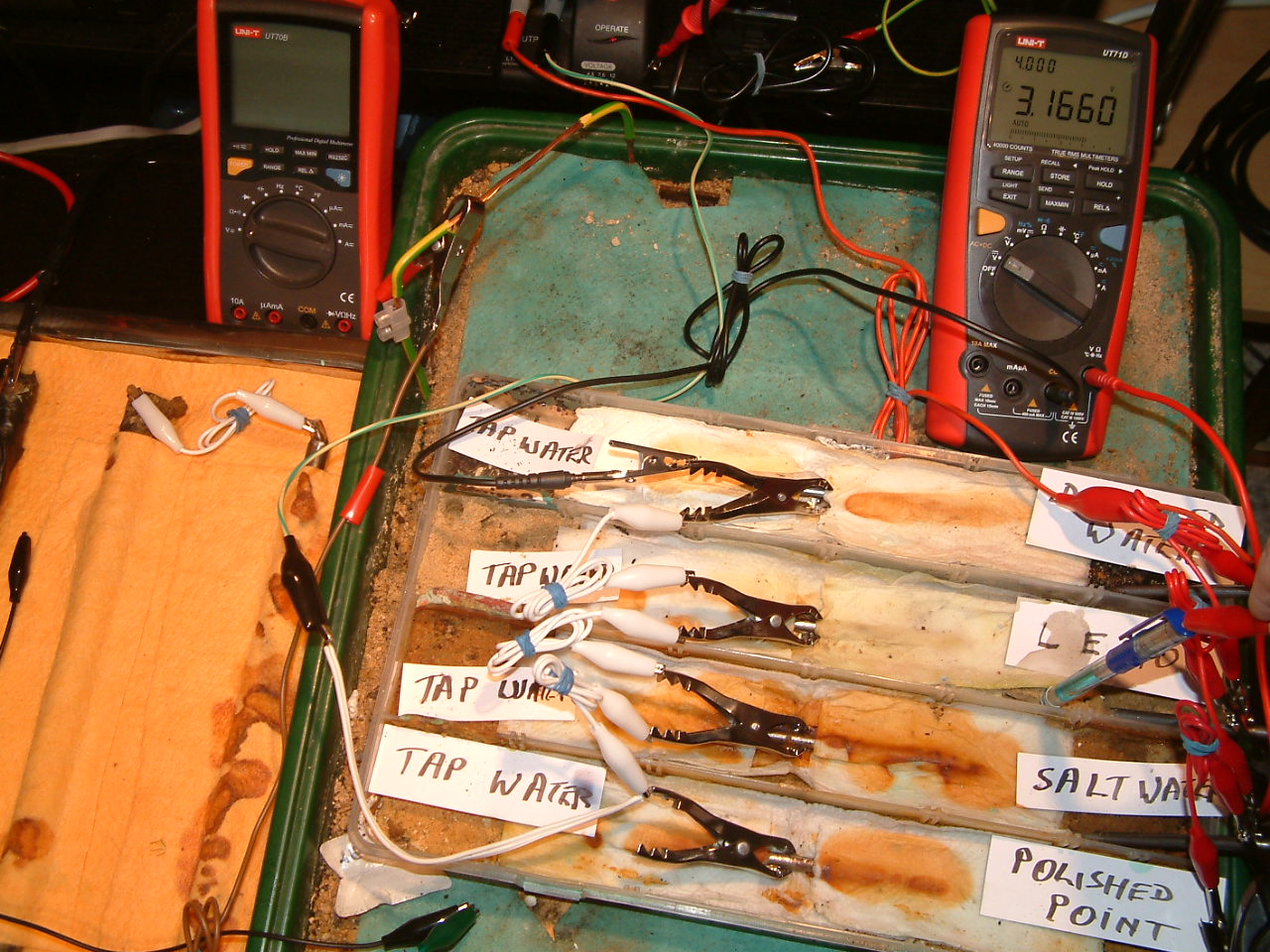
pipe-to-soil 42
The power supply is energised and the potential difference between the copper/copper-sulphate electrode in partition two and the subject nails is now 3.1660v.
pipe-to-soil 43
The power supply is energised and the potential difference between the copper/copper-sulphate electrode in partition two and the subject nails is now 3.1660v.
It can be seen from this demonstration that the voltage variations that have been called the 'IR drop in the soil' are really due to the probe being in the incorrect position to obtain the measurement that is required by science.
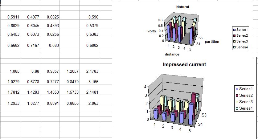
This measurement must be taken at the interface between the ANODE of a corrosion cell (the working electrode) and the electrolyte.
The closest that we can get to this in these tests is where we can see the corrosion products and if we push the probe closer to the metal we will disturb the reaction that we are trying to measure.
However, when we look at the electrical pressures that result from the natural corrosion in our test we find that the highest readings are in pipe-to-soil 8 where the voltage is 0.7167v. this might be due to the energy being discharged from the corrosion reaction from the part of the first nail. This is NOT what should be expected as this part of the nail was not corroded when examined later.
This test seems to show that it is not possible to judge the corrosion status of metal by measurements made in this way. The difficulty is that cathodic protection stops the corrosion reaction.
If the impressed current system has stopped corrosion then the anode does not exist as it has ceased 'working'. It is the state of equilibrium in which the anode stops reacting that we need as a criterion for cathodic protection, as this is when corrosion has stopped.
Email Cathodic Protection Network International Limited