The Isopotential Cell
ABSTRACT
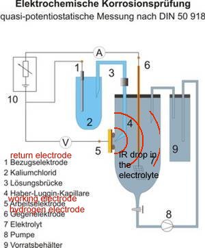
Cathodic protection theory depends on a voltage measurement taken between the subject metal and a reference electrode placed at the interface between the metal and the electrolyte. This is achieved in the laboratory by using a capillary of inert, but conductive material, such as agar-agar.
The isopotential cell is based on this principle but adapted for cathodic protection field use. Several versions of this have been suggested in continental Europe, but this is a simple version that has been tested extensively in the field since the mid 1980's.
INTRODUCTION
It has now been recognised that there are inherent errors in voltage measurement obtained by the established cathodic protection monitoring techniques. The 'immediate off potential' method is one attempt to remove these errors and the 'isopotential cell' is another, developed by several researchers who specialise in cathodic protection monitoring.
THE NAME 'ISOPOTENTIAL CELL'
The term 'isopotential cell' is adopted in this study as a convenient expression of the workings of the arrangement, which creates a position, in which to place the electrode, which is at the same potential as that at the interface between the electrolyte and the subject metal.
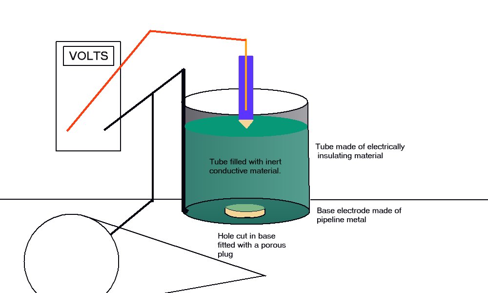
THE ARRANGEMENT
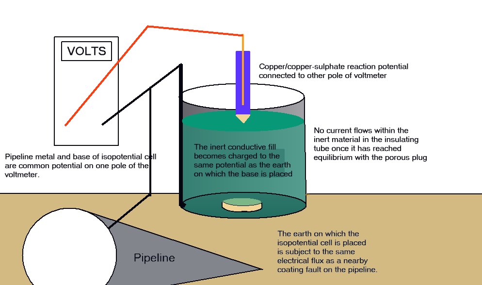
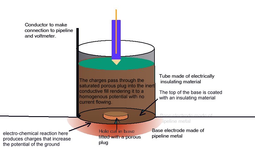
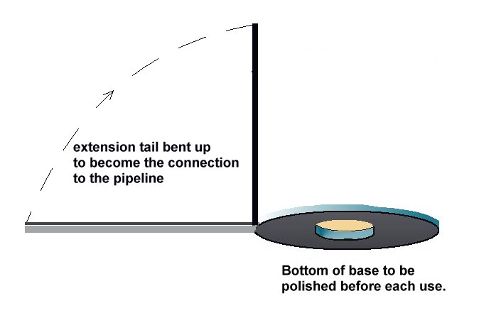
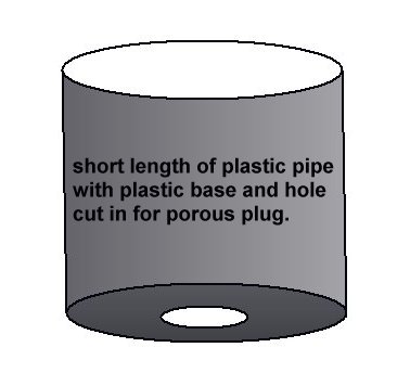
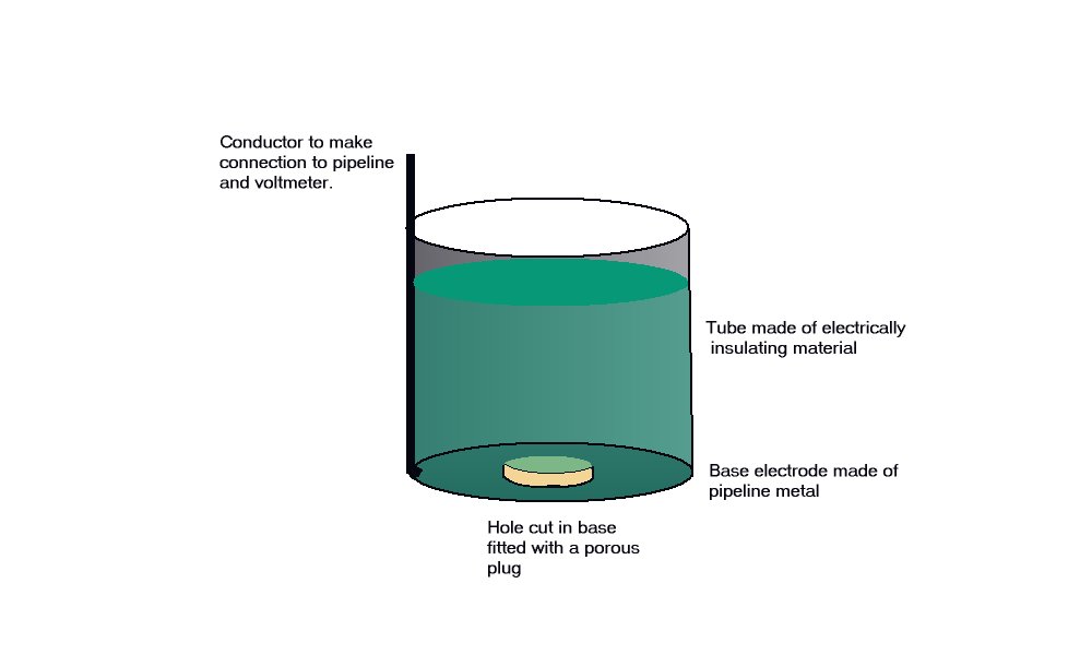
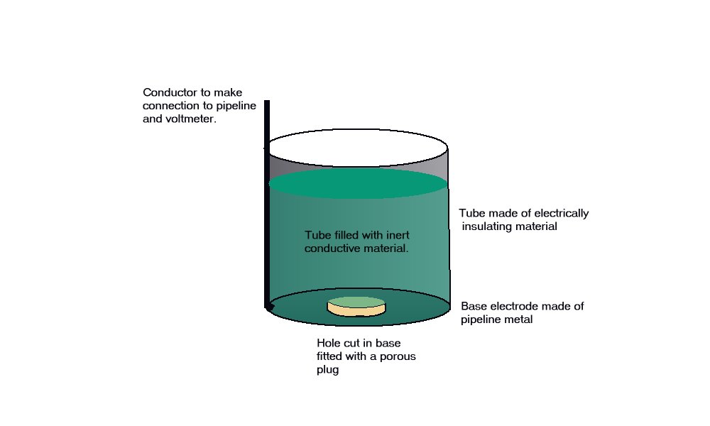
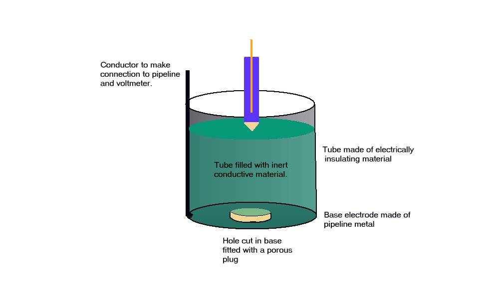
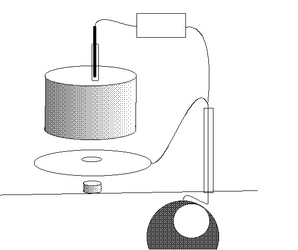
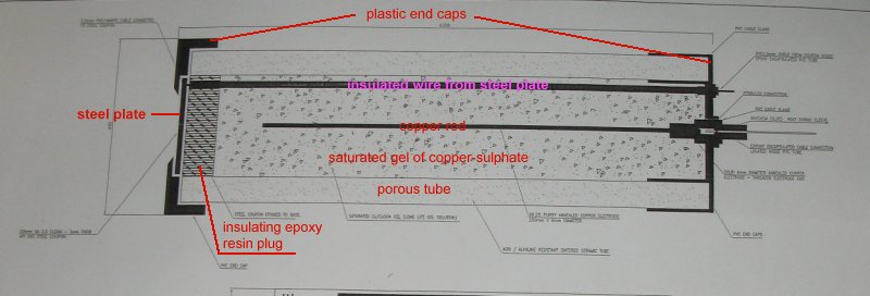
A porous plug is fitted into the hole in the centre of a steel coupon which is used as the base of a plastic tube containing an inert fill. The inside surface of the coupon is coated with an insulating material and there is provision for electrical connection to the coupon metal. The exposed metal of the coupon is placed firmly on the ground, as the base of the cell, and connected to the pipeline, via a conductor. The pipeline is connected to a high impedance voltmeter the other pole of which is connected to a copper/copper-sulphate electrode. The porous plug of the electrode is placed in the open top of the plastic tube containing the inert fill, thus completing the measuring circuit.
THE EQUILIBRIUM OF THE CELL
The reaction of the metal of the coupon to the electrolyte surrounds the porous plug which is saturated by and directly connected to the inert content of the plastic tube. The potential of the porous plug is reflected by the potential of the inert fill instantaneously, but not further current flows through this fill after equilibrium is reached.
This is an identical status to that of a Lugin Capillary in a laboratory and the electrode placed in this situation can be regarded as a 'reference electrode', whereas in normal cathodic protection work it is only an earth contact electrode.
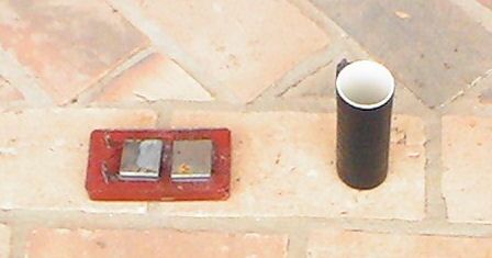
How to make the general purpose field survey Isopotential Cell
You will need steel similar to that of which the subject structure is made.
You will need a short piece of plastic pipe and a flat piece of plastic to fit the end.
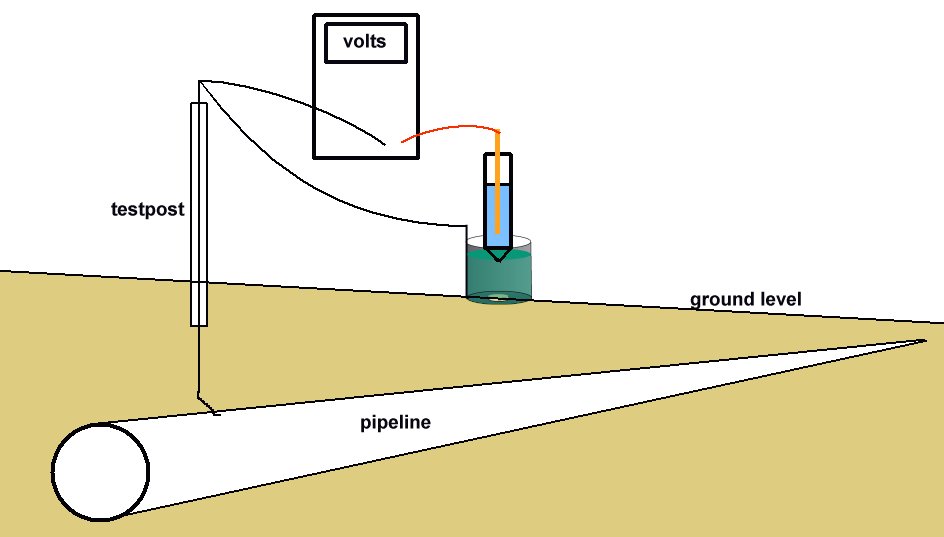
PROCEDURE TO USE THE CELL
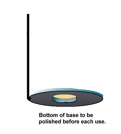
The bottom of the coupon is cleaned to bright metal and placed on the ground as close to the pipeline as possible.
The high impedance voltmeter is connected between the pipeline and the electrode which is placed in the top of the plastic tube. The coupon is connected to the pipeline and the voltage on the meter is noted.
INTERPRETATION
It has been acknowledged that the true interface potential of the pipe can only be obtained from an isopotential cell placed at the pipe position and it is recommended that facilities are permanently installed for this purpose.
Voltages measured with the isopotential cell are invariable much lower than conventional 'pipe-to-soil potentials' with the cathodic protection system on. The reading will be similar to an 'immediate off potential' reading, as the use of the isopotential cell removes the errors caused by the passage of the cathodic protection current.
EUROPEAN CONTINENTAL APPROACH
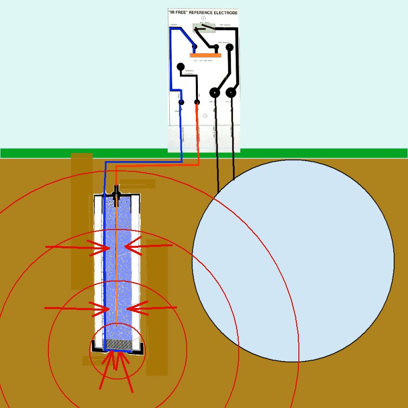
These devices are connected to the pipeline and the electrode can be regarded as a standard reference because the arrangement of the device ensures a constant physical relationship, which is necessary in measuring reaction potentials.
I have made and tried a variety of arrangements that follow the same principles but the results do not agree with those predicted by the design and theory.
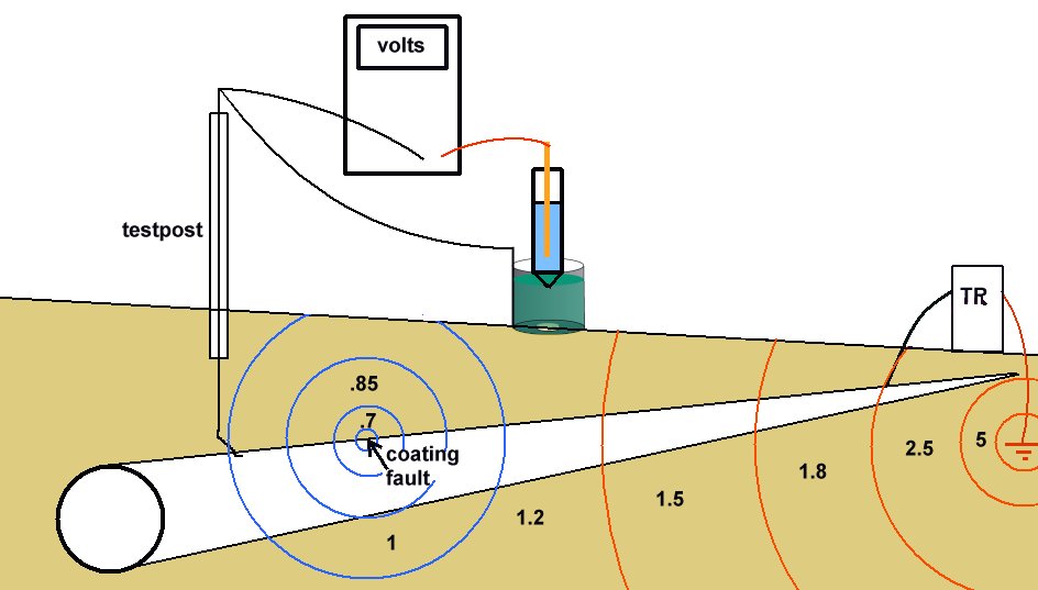
On examination, it can be seen that these devices miss the point that required measurement must be made at the anodic interface between the metal and the electrolyte to avoid what the scientists refer to as the IR drop.
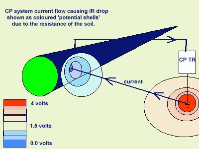
THIS IS NOT THE SAME AS THE FEATURE THAT CATHODIC PROTECTION ENGINEERS 'IR DROP ON THE SOIL'.
The IR drop in the soil refered to by cathodic protection specialists is in fact a voltage between two points of soil contact. It is more accurately described as a potential gradient because a voltage is the difference between two potentials.
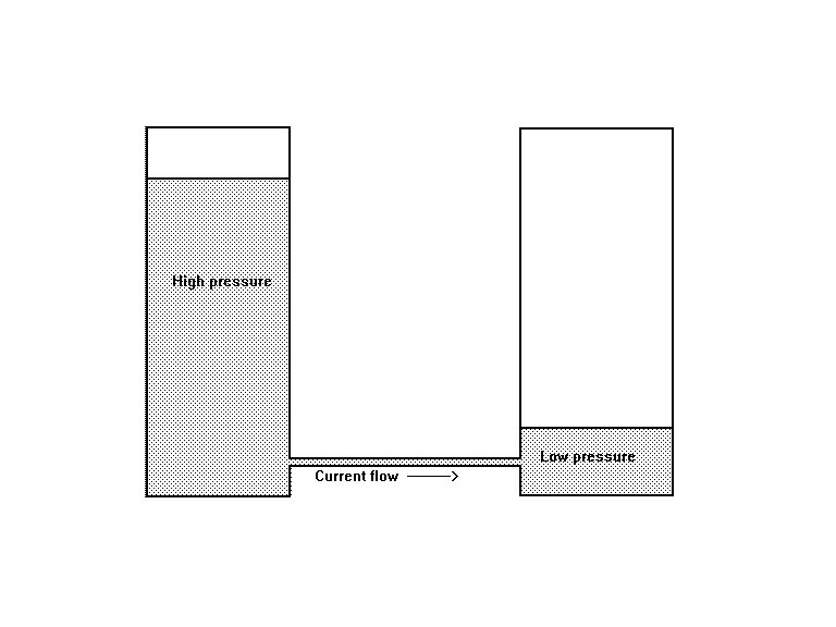
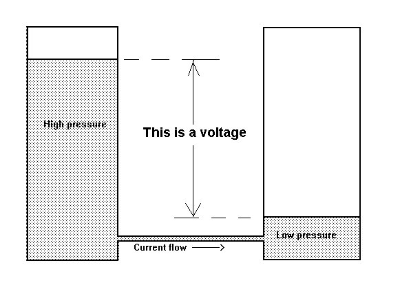
It is very important that cathodic protection engineers recognise that a voltage requires a zero and that a standard Cu/CuSO4 electrode does not provide a zero when placed in the electrolyte between the anode and cathode of a corrosion circuit.
A cathodic protection circuit is a corrosion circuit superimposed over other corrosion circuits and influenced by all of the electrical flux in the ground.
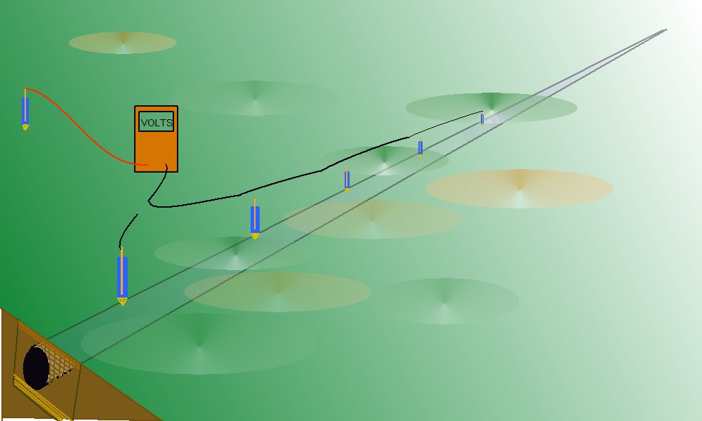
A standard Cu/CuSO4 electrode can be used as a reference potential if placed in a fixed position, remote from all influences that affect the pipeline.
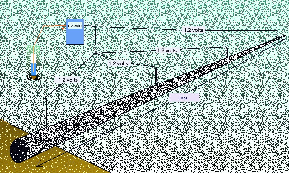
This procedure was used in North Thames Gas in the mid 1980's to prove that the pipeline potential can regarded as constant throughout the whole length of a normal CIPS or DCVG survey. This is because the resistance of the pipeline is a fraction of a percentage of the other resistances in the measuring circuits.
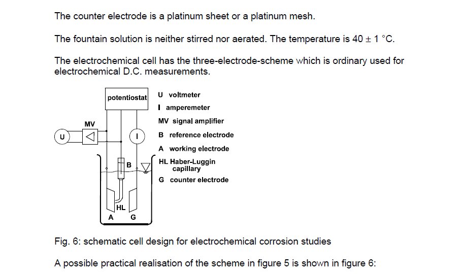
The measuring circuit that is capable of rendering a criterion for cathodic protection has been described and drawn in many scientific papers.
It is easy to relate these tests to field practices as they all rely on simple voltmeters to make the measurement.
The complications arise in the minds of those who do not understand a 'potential' only has a value in relation to another potential. Everything has an electrical potential and this has been described in physics by 'Gibbs Free Energy' in a similar way to gas filling every available space.
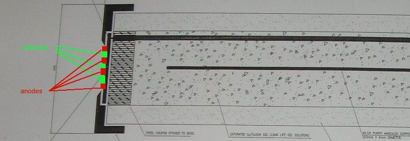
When we are making a voltage measurement it must be relative to the Electro-Motive-Force produced by the corrosion reaction occuring at the ANODIC interface with the electrolyte.
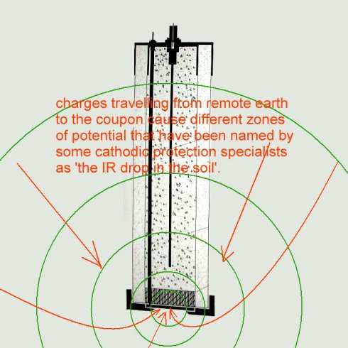
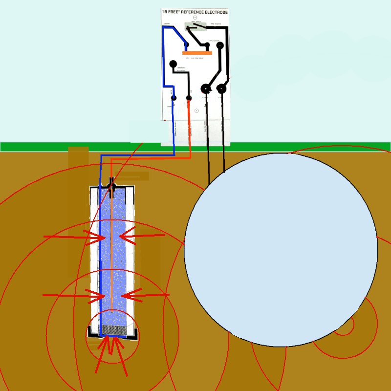
In the case of the coupon and electrode arrangements proposed in these diagrams it can be seen that reference electrode is well outside of the zone in which the potential of the electrolyte is subject to the charges resulting from the electrochemical reaction.
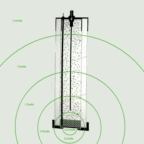
The reference electrode is in fact in an undefinable and immeasurable potential zone.
This is easily seen when considering it's relationship with the pipeline metal as well as the reference/coupon arrangement.
It was in consideration of all these facts that I devised the Alexander Cell in which arrangement the reference electrode can be placed in the correct zone of potential and the measurement can be confirmed by a measurement of actual corrosion current.
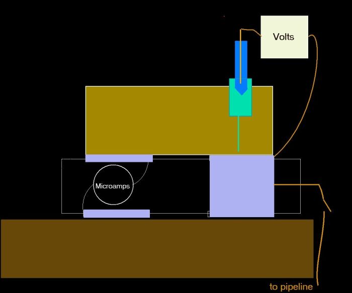
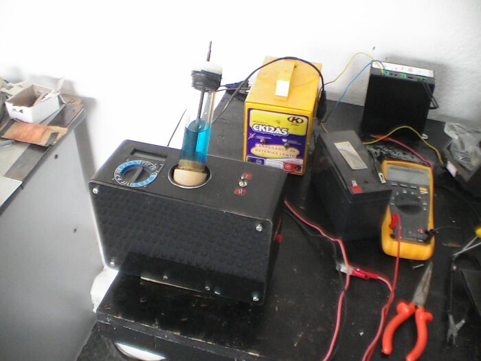
This is the scientific model of the Alexander Cell made at the Guararema Training and Research Centre, Brazil.