
The Alexander Cell
How to make the general purpose
field survey Alexander Cell
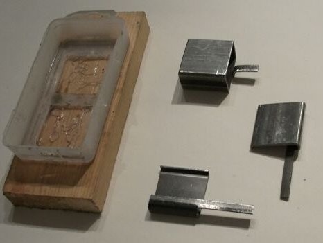
You will need steel similar to that of which the subject structure is made.
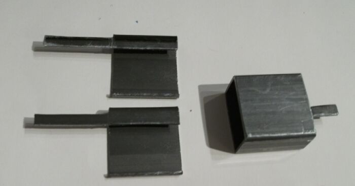
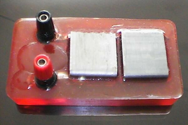
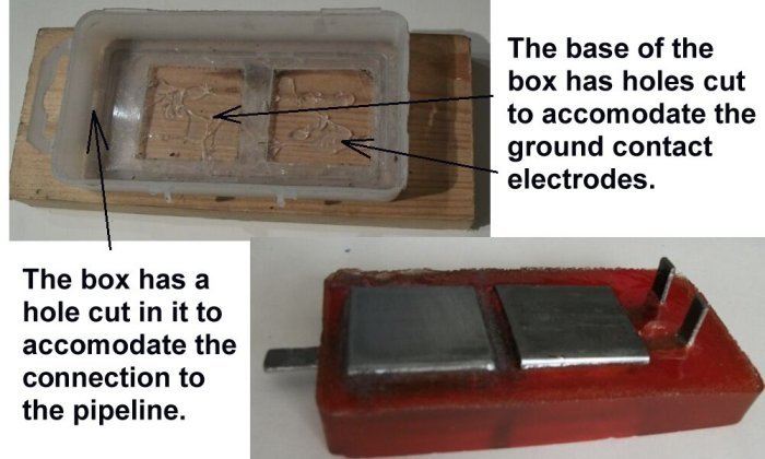
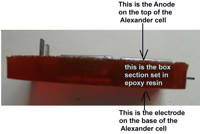
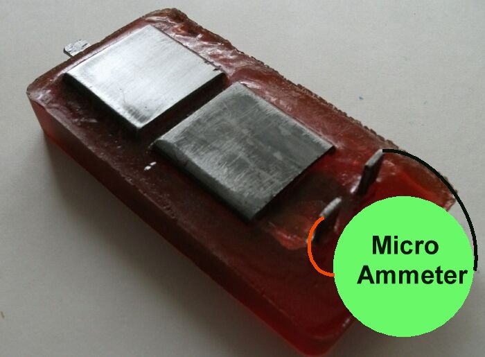
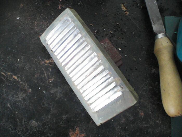
I bought a small 'box girder' (I don't know the proper name for it) and cut it in such a way that the contacts protrude from the epoxy resin body.
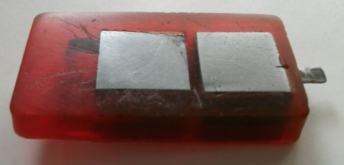
You will need three pieces as one of them serves the purpose of two of the four electrodes in the finished article.
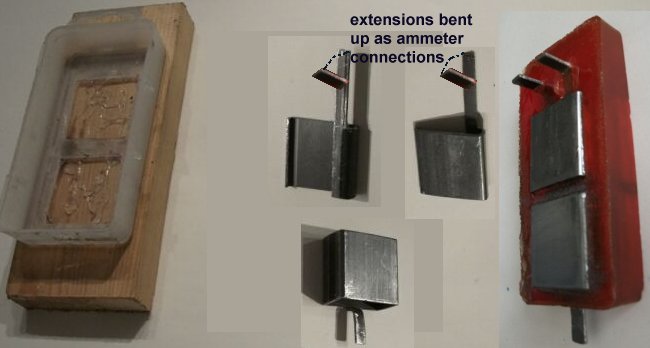
The mould can be any suitable plastic/nylon box into which the coupons can be placed while the resin sets.
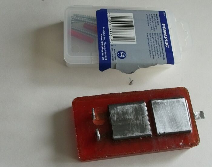
(This was a nylon box, retailing screws and plugs.)
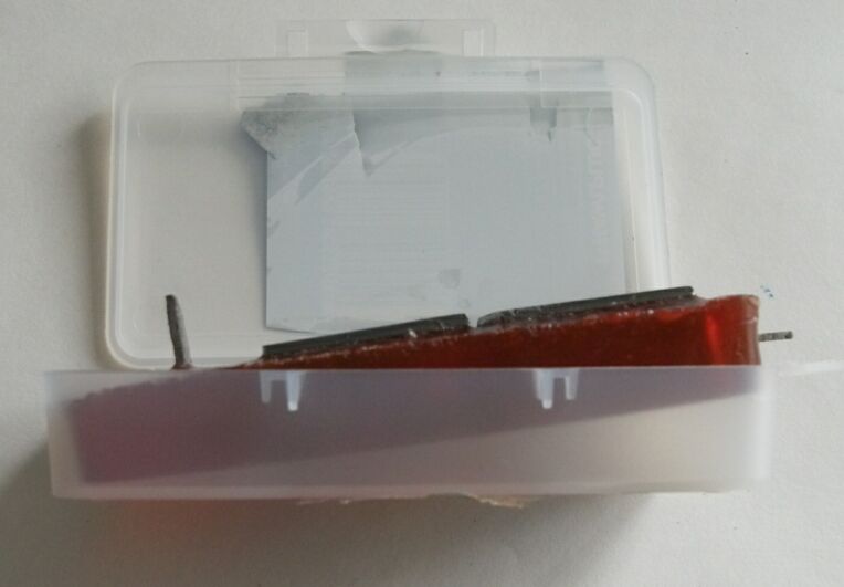
It was cut to accomodate the coupons while the resin was poured in.
It is important to insulate each coupon from the others while pouring the epoxy in.
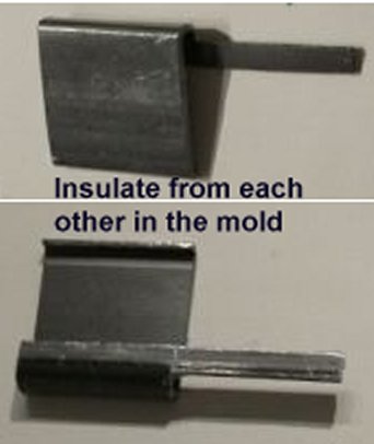
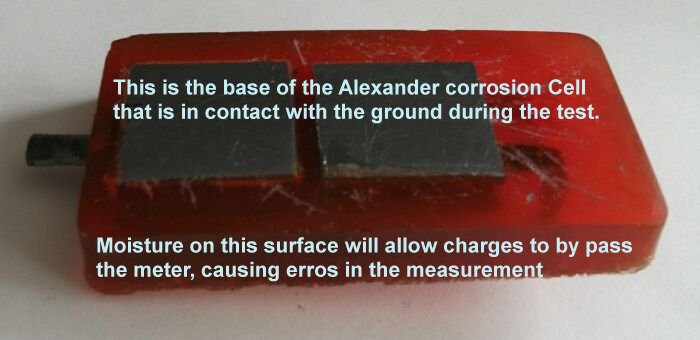
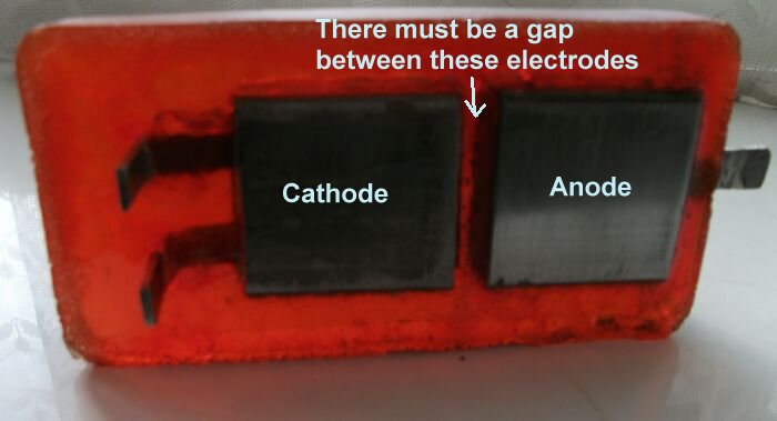
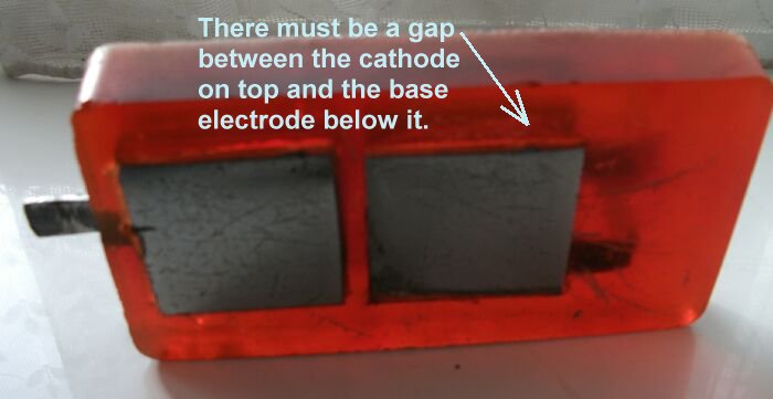
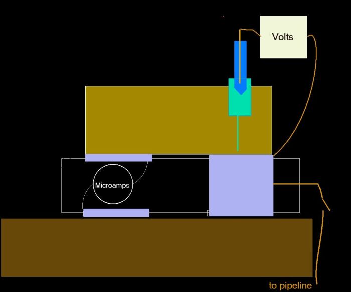
It is important that the Cathode on top of the Alexander Cell is electrically separated from the ground electrode that is immediately below it on the base of the unit.
I found that splitting some insulation from a cable could be placed over the cut edges of the coupons to isolate them from each other.
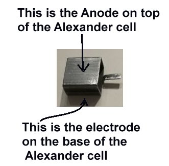
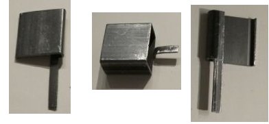
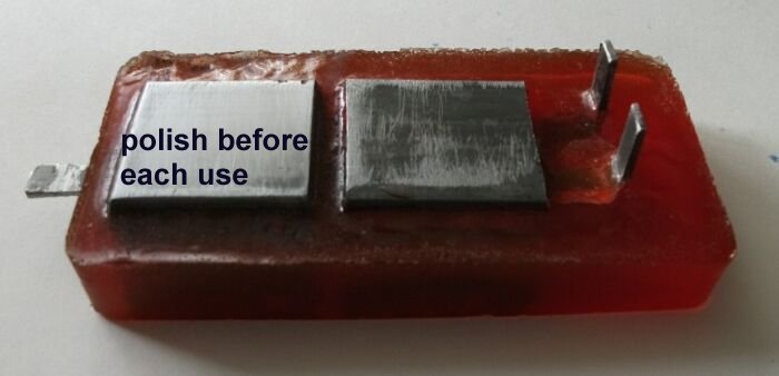
The 'box' coupon serves as the anode on top of the device and the receiving electrode from the ground. It must be polished before each use.
The polishing of both base electrodes makes equal contact with the ground.
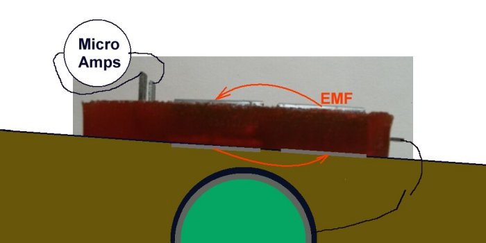
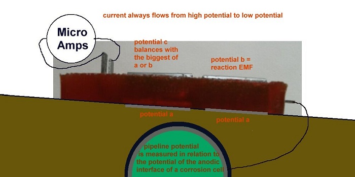
Polishing the anode on top of the Alexander Cell allows the electrochemical reaction to generate an EMF that drives the corrosion current through the sample of electrolyte to the cathode of this cell.
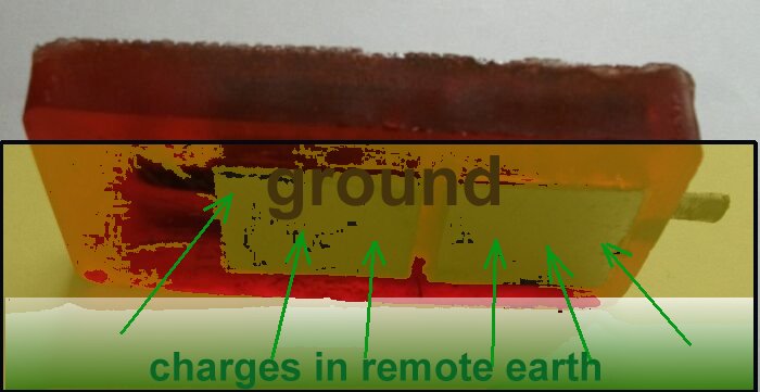
The only available path for these charges to complete the corrosion circuit is through the meter and the ground.
Current is only measurable in a 'closed circuit' condition., but the Alexander cell allows the current passing into 'mass earth' and received from 'mass earth'to be measured.
The extensions of the cathode and the first base electrode must be bent up to allow connection through the ammeter.
It is important to know that cathodic protection current will ALWAYS enter the subject structure metal at the cathodic interface but the direction of flow through the anodic interface is determined by the density of charges in the electrolyte being greater than the charges produced by the corrosion reaction.

It is thermodynamicly impossible to remove all charges from anything because a guy called Gibbs wrote an equation known as 'Gibbs Free Energy' that applies to the whole universe and everything in it.
Another guy called Nernst wrote another equation that described balance between metal and electrolyte and a guy called Pourbaix drew some diagrams that show how corrosion can be pacified.
All of these can be verified using the Alexander Cell but they mainly depend on a value of a potential.
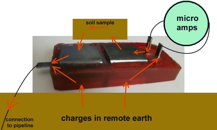
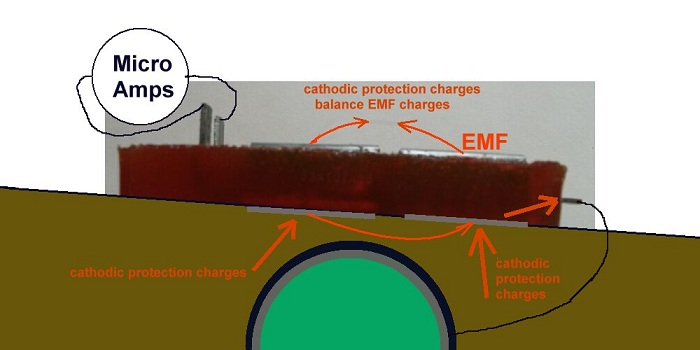
When the anode of the Alexander cell is connected to the subject structure the charges in the cathodic protection circuit and all other ground potential flux have a path to the subject structure that is similar to a coating fault of the area of the two base plates.
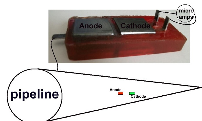
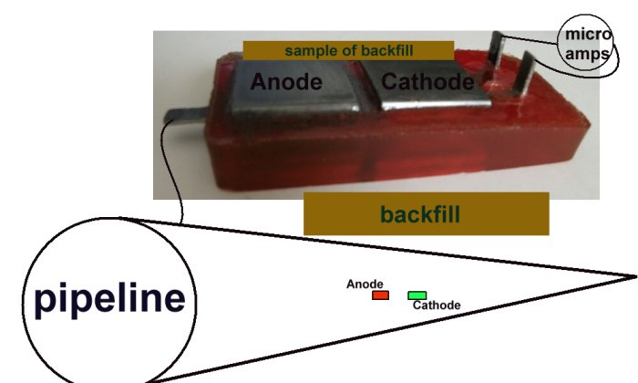
A sample of the backfill bridges the anode and the cathode on top of the cell and the base electrodes complete the corrosion circuit.
The Alexander Cell allows the charges from remote earth to enter the pipeline through either the anode or the cathode of the Alexander corrosion Cell. This is exactly the manner in which cathodic protection charges enetr the pipeine through a natural corrosion cell at a coating fault.
The Alexander Cell allows a whole corrosion cell to be influenced by the electrical charges, locally available, from the cathodic protection system and the effect of this influence can be seen on a current meter in a closed circuit condition.
This allows the current density to be calculated (if that is important).
I hope these pictures will allow you to see how to make this model of the Alexander Cell.
I would like to receive reports of resulting usage and will help to explain how to diagnose the true corrosion status of your structure.
It can be seen that there is no other source of current than the EMF of the corrosion reaction itself.
You can check the Alexander Cell before use to make sure that there is OL on the resistance reading of your meter.
If there is not then you should clean and dry all surfaces to make the sample electrolyte completley isolated from the ground. This is what makes it into a closed circuit current or potential measurement.
On examination, it can be seen that other devices miss the point that required measurement must be made at the anodic interface between the metal and the electrolyte to avoid what the scientists refer to as the IR drop.
THIS IS NOT THE SAME AS THE FEATURE THAT CATHODIC PROTECTION ENGINEERS 'IR DROP ON THE SOIL'.
The Alexander Cell works on exactly the same principal as a long term 'weight loss, corrosion coupon' but has the advantage of giving an immediate result, based on Faradays Law, which relates the amount of current to the weight of metal going into solution.(going rusty)
I supplied a field model of the Alexander Cell for testing by Dick Baxter, a NACE qualified corrosion engineer and it was used in confines that resulted in a directional cathodic protection current flow.
Everybody knows that this situation can never be experienced in field work of any kind.
However, the matter of bench experimentation had been raised and I desgned a model of the Alexander cell resolve the issue of 'current density' or charge diffusion in confined spaces.
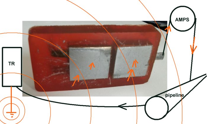
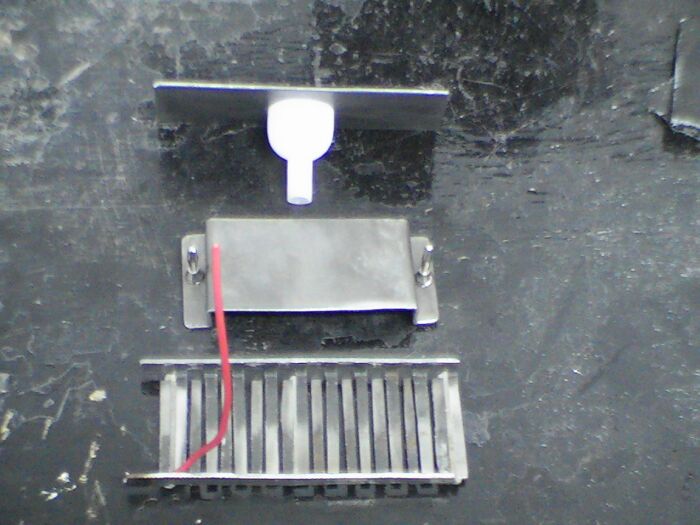
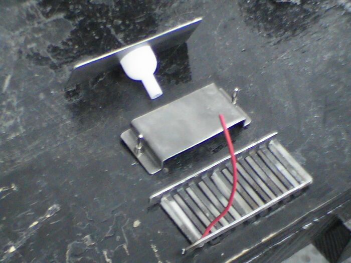
In this version the two base electrodes are split into a comb like arrangement so that the current can enter either anode or cathode regardless of direction of source.
A connection is provided to connect the whole cell to the pipeline in such a way that the cathodic protection current may influence both cathodic and anodic interfaces, as it would in the case of a natural corrosion cell on the surface of the pipe.
This matter had been raised and resloved in the mid 1980's when the National Physical laboratory of the UK produced a critical report that had to be withdrawn when Jim Gosden, the chairman of BSI Committee CP1021 pointed out 17 scientific inaccuracies. At this time he reviewed tha Alexander Cell and raised the issue of the directional current in the lab.
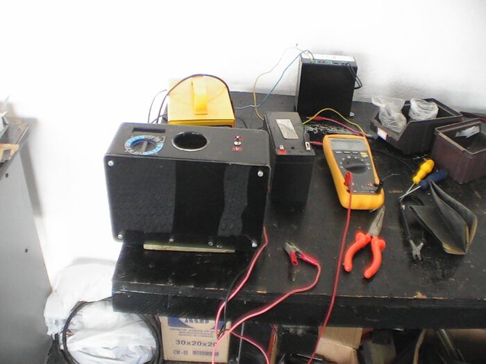
Using the Alexander Cell in the field
The Alexander cell is cleaned and dried to make sure that current does not leak through moisture on the sutface of the epoxy resin block.
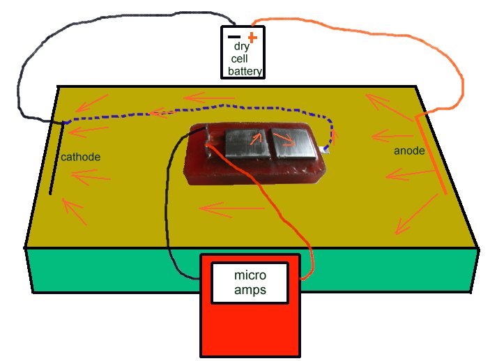
It is then connected to the micro-ammeter and placed on the ground showing no current flow.
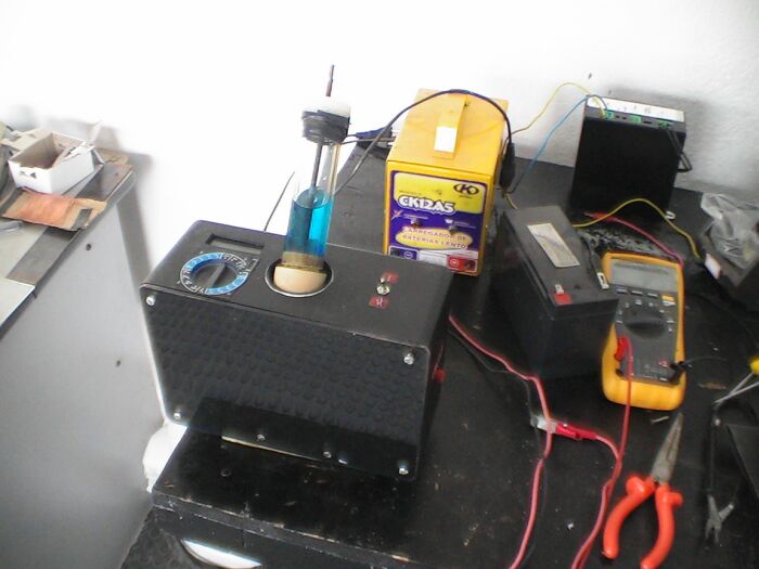
A sample of the backfill is made wet with distilled water so not to alter the chemical composition, and wrapped in clean washed cloth that will add no reaction to the process.

The sample is placed bridging the two electrodes on top of the Alexander Cell and the operator can see the corrosion current due to the EMF of the reaction on the bright steel surface.
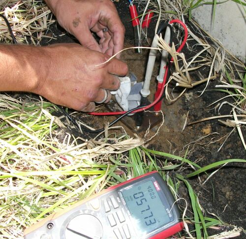
This current varies as the chemicals in the sample disolve the metal of the anode and the value and direction should be noted.
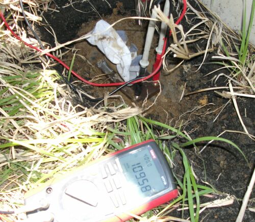
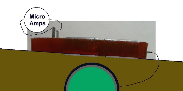
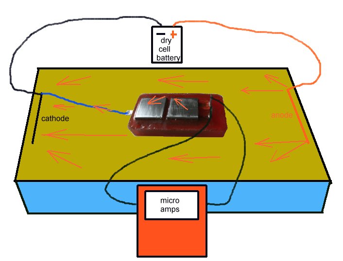
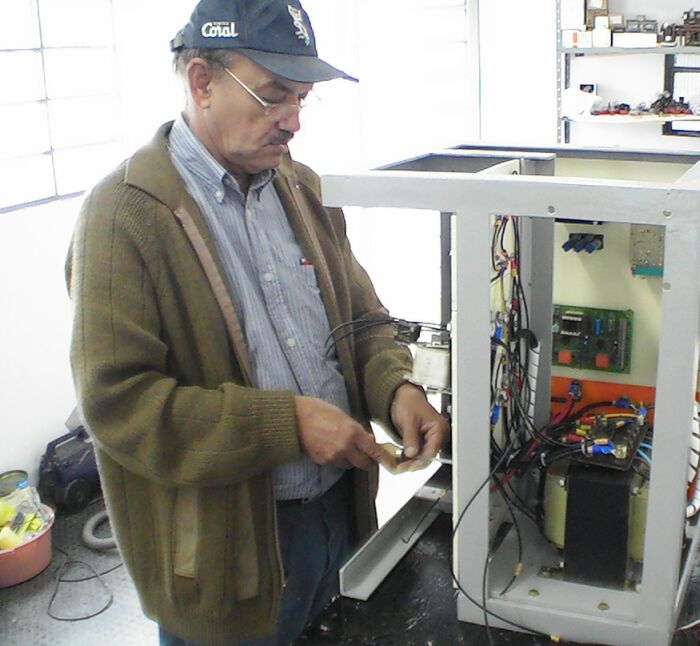
The cell is connected to the pipeline, while watching the meter, and the changes in the behaviour of the current are noted.
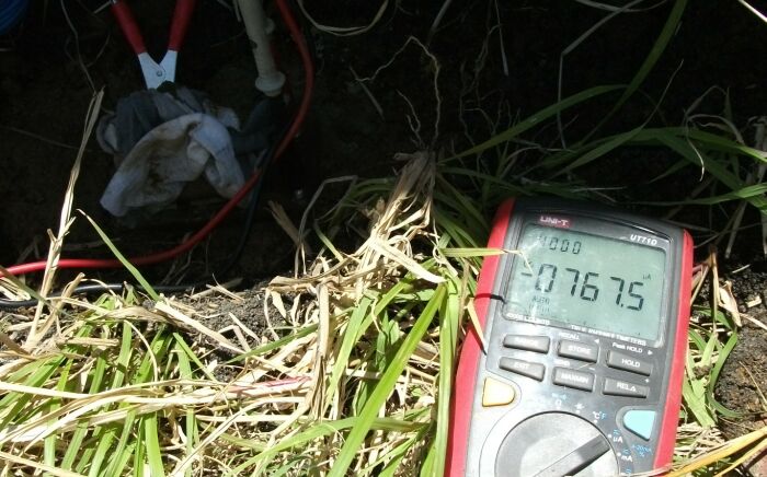
It can be seen that the direction of the current has changed in this case and this has been caused by the lowering of the potential of the Alexander Cell to below it's corrosion potential.
It is important to know that cathodic protection current will ALWAYS enter the subject structure metal at the cathodic interface but the direction of flow through the anodic interface is determined by the density of charges in the electrolyte being greater than the charges produced by the corrosion reaction.
It is thermodynamicly impossible to remove all charges from anything because a guy called Gibbs wrote an equation known as 'Gibbs Free Energy' that applies to the whole universe and everything in it.
Another guy called Nernst wrote another equation that described balance between metal and electrolyte and a guy called Pourbaix drew some diagrams that show how corrosion can be pacified.
All of these can be verified using the Alexander Cell but they mainly depend on a value of a potential.
In order to clarify this to the satisfaction of the scientific community I have designed another version of the Alexander Cell and someone paid for me to have the patent application in my name.
The pictures that follow are included in that application so I have what they call a 'priority date' so you can all go ahead and make it with my permission.
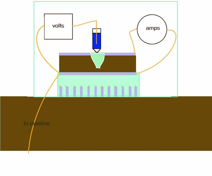
This is a practical schematic that I designed to work of with Victor and Adraina at the Cathodic Protection Network, Guararema Training and Research Centre in Brazil.
Adriana designed and made the base plates and Victor came up with the anode plate being detacheable to allow for polishing before each useage.
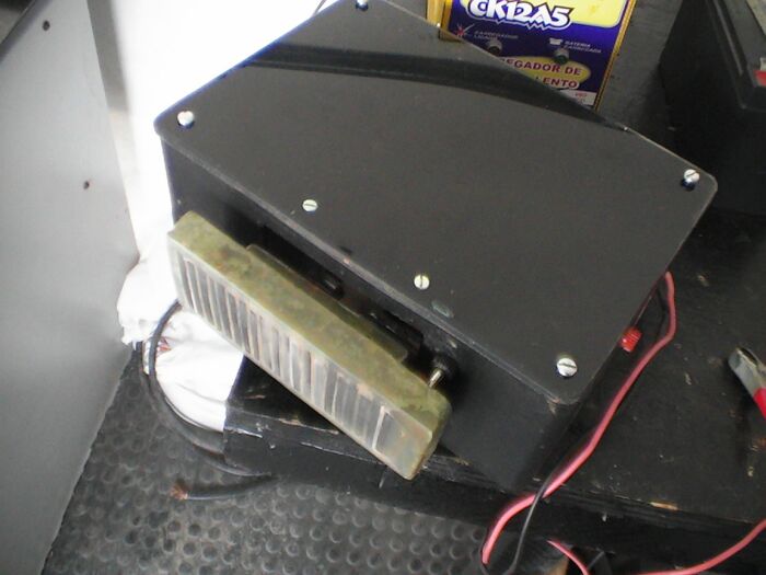
It can be seen that the two base plates are like combs that do not touch, but that connect to correctly to the body of the Alexander Cell when plugged in.
This shows the base plate combs and anode set on a block of epoxy resin. Victor and Adriana did this in a mold they made.
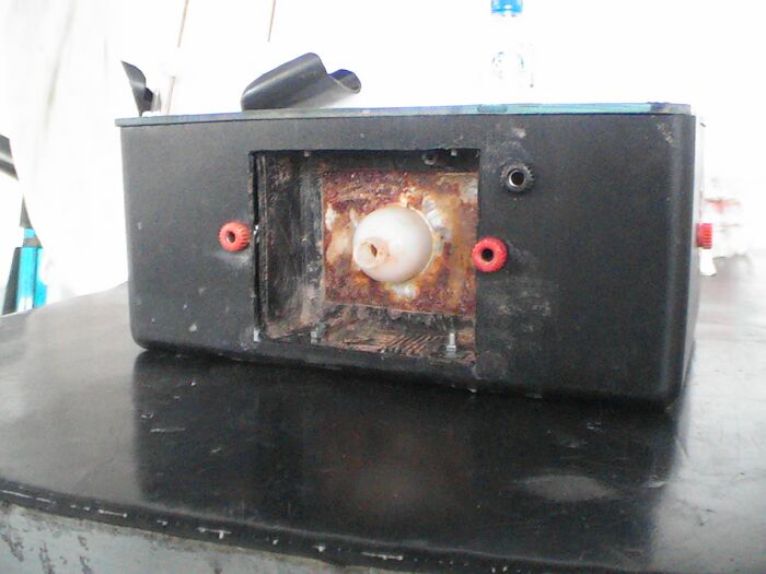
It is important that the cathode on top of the Alexander Cell is never polished but merely washed of debris and this picture shows that this is achieved by a deep cavity in which the electrolyte sample is housed.
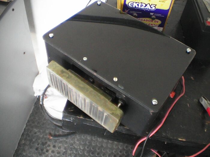
This shows how the base is plugged into the Alexander Cell when the sample has filled the cavity.
The two plugs make insulated electrical contact with an ammeter and a voltmeter.
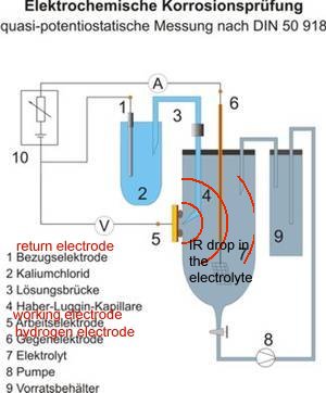
Access is provided for a reference electrode of choice to contact an inert gel at the top of a plastic 'lugin capillary' to the interface between the anode and the sample of electrolyte.
This arrangement is identical to that describe in DIN 50918 and this version of the Alexander cell can be used in the field as well as the laboratory.
sadly, Victor died of cancer a few months ago.
I did not speak his language but we were great friends.
Google Translate and I miss him, and this page is dedicated to him.
INTERPRETATION
The reactions at the two base electrodes are similar and their reactions to the ground are balanced.
The potential difference between the anode and the cathode is the sole cause of the current which flows through the measuring circuit during the first stage of the procedure.
The potential of the bright steel anode is made equal to that of the pipeline through a low resistance conductor.
When the Alexander Cell is connected to the pipeline, the potentials of all the metal components are made equal to that of the pipeline, through a low resistance conductor.
If this new potential is sufficiently low, the current will reverse direction through the Alexander Cell meter. The reaction at the interface cannot continue, as current cannot pass in both directions at the same time. Micro cells on the surface of the anode will also be lowered below their corrosion potential and be passive, according to the laws of thermodynamics.
If this new potential is sufficiently low, the reaction at the anodic interface cannot continue.
This reaction has been the sole cause of the original reading on the meter.
Any current flowing in the opposite direction must be that resulting from the connection to the pipeline.
This current is seen to be passing against the corrosion current, which must have been stopped.
The current passing onto the pipeline is returning to the negative terminal of the cathodic protection source. In this way the ALCE demonstrates that there is sufficient current density at this location, to prevent corrosion current passing from the anode of a corrosion cell into the electrolyte.
The cathodic protection current density is seen to be sufficient to stop the reaction of a corrosion cell at this location.
Impressed current systems can be adjusted to watch the current being stopped, and sacrificial anode systems can be analysed to show the exact area of influence of each anode.
As the corrosion reaction is the sole cause of the original reading on the meter, then it may be safely reasoned that the reaction has stopped when this current has stopped.
If there is no current being discharged from the metal to the electrolyte then no metal can go into solution (Faraday).
ACTUAL MEASUREMENTS
On the 2nd of December 1992, before excavating the pipe the ALCE showed a corrosion current of 26 micro-amps which was stopped by the cathodic protection when connected to the pipeline.
On the 3rd of December 1992 a further ALCE test was made in the excavation, when the corrosion current was 26.7 micro-amps which reversed to -21 micro-amps on connection to the pipeline.
Both of these tests indicate that the current density at this location is sufficient to enable corrosion to be stopped by the cathodic protection system.
The control sample, found in the backfill, demonstrates that corrosion will take place, as indicated by the ALCE, and the condition of the pipeline confirms that corrosion current can be stopped by the current density in this vicinity.