Cathodic Protection Network International
CATHODIC PROTECTION NETWORK INTERNATIONAL
74 DALCROSS
BRACKNELL
BERKSHIRE
RG12 0UL
Static ground potentials
Used batteries set in a flight case
Case study
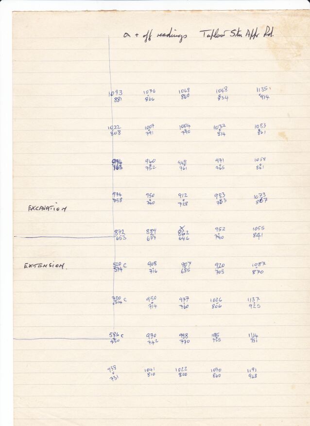
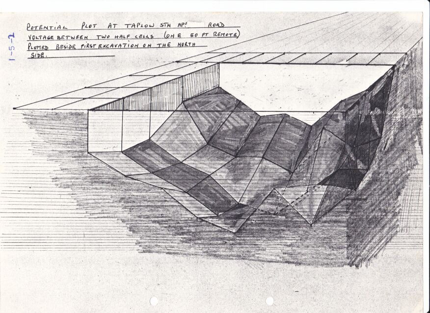
At a site near to Taplow Railway Station in the UK a steel gas pipeline passed under the railway, a road and a river. Upstream from these crossings a combined DCVG and CIPS survey showed a 'pipe-to-soil potential'(really a voltage) showed an 'on' reading of -0.650v when the copper/copper-sulphate electrode was over the pipeline that had about 3 meters of cover. History indicated that this area had been used for fly tipping of rubbish and I was sent to carry out an investigation using the techniques I had developed and the Alexander Cell. I reported that about .3 meter patch of coating was missing and that there would be no corrosion as the Alexander Cell showed that the cathodic protection was effective.
A contractor was sent in and another technician told him where to excavate.
They culd not find a coating fault and I was asked to return to the site and tell the contractor where it was.
They extended the excavation 2 meter upstream and found exactly as I described.
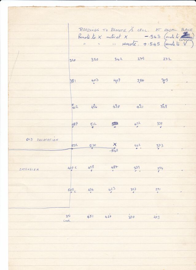
During my investigation I had identified a location 2 meters off center that had a pipe-to-soil voltage of -0.600 with the cathodic protection on.
I asked that this spot was investigated while the digger was there but this was refused.
I submited the report but this was just quietly filed so I sent a copy to the head engineer of British Gas and got a very strong wrning not to do this again.
I found that I could create this effect and built it into the training centre a Guararema SP Brazil and demonstrated it to Valdir, the owner, and Jose Ribeiro. It is still there and can be demonstrated.
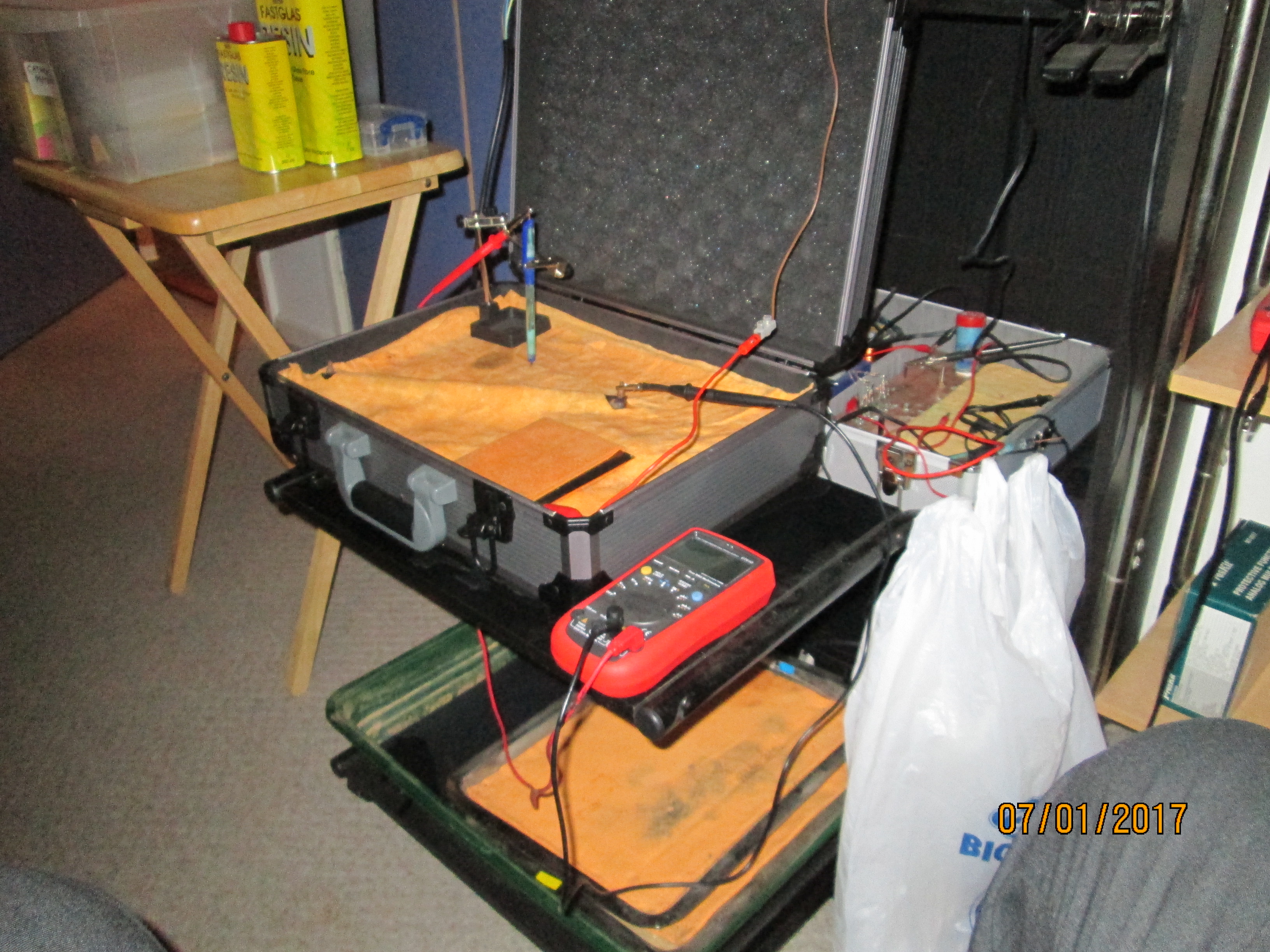
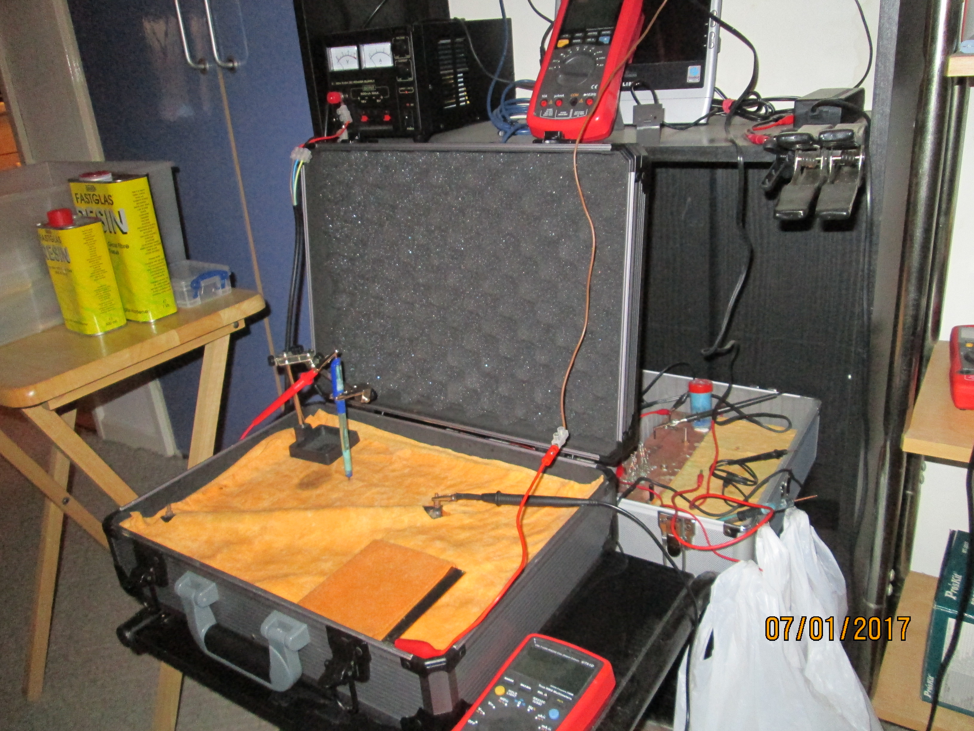
I have made small models of this and the flight case in the picture is an extension of this modelling.
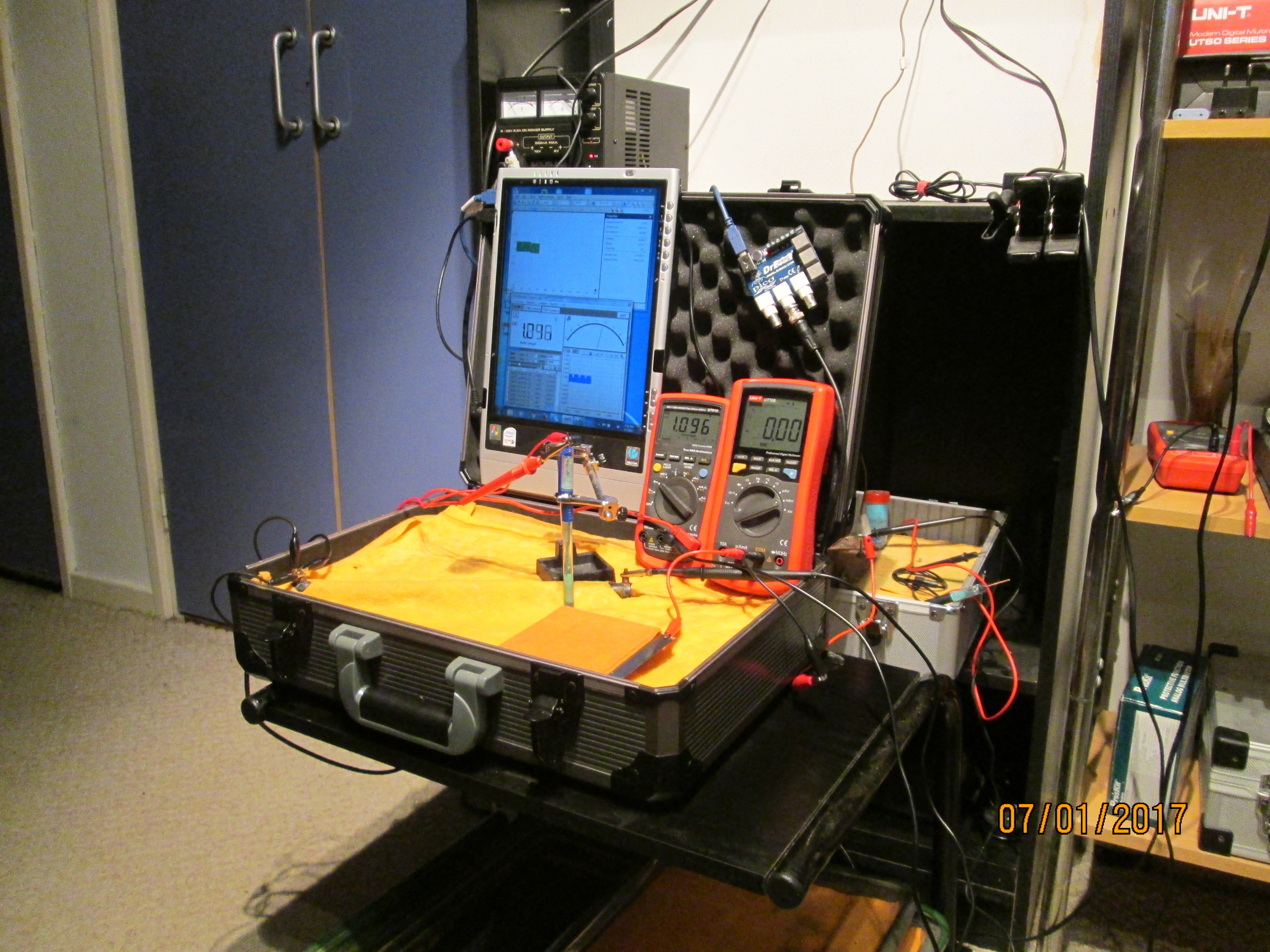
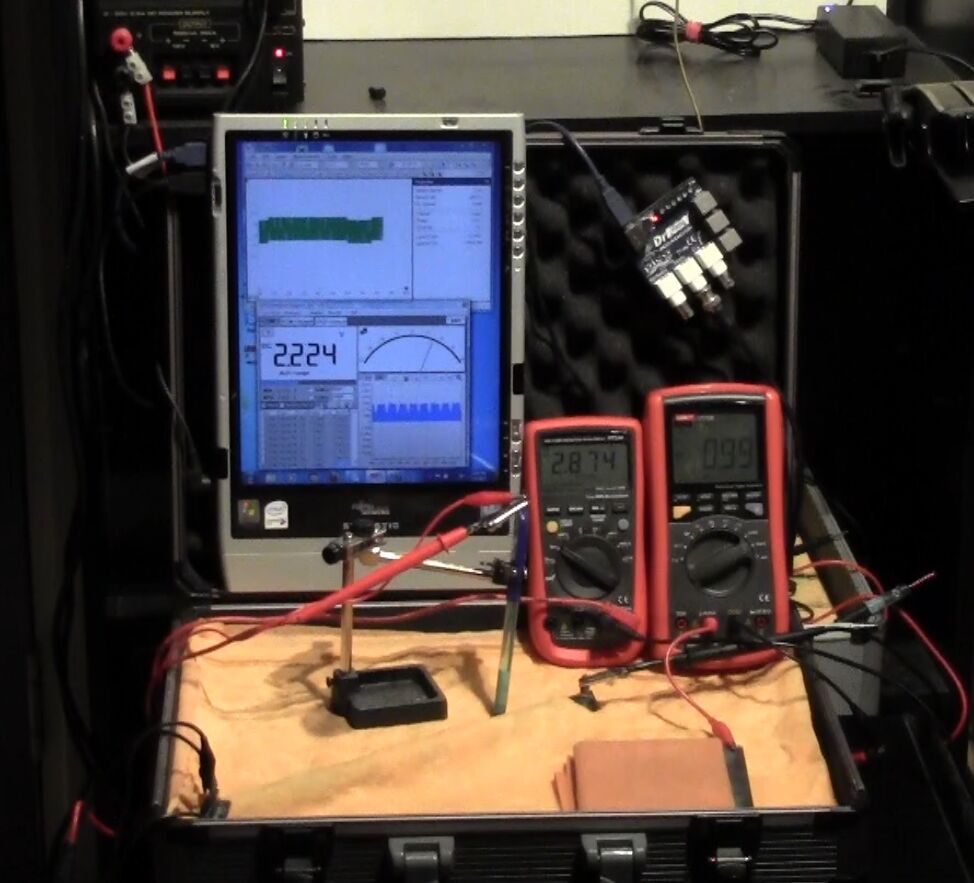
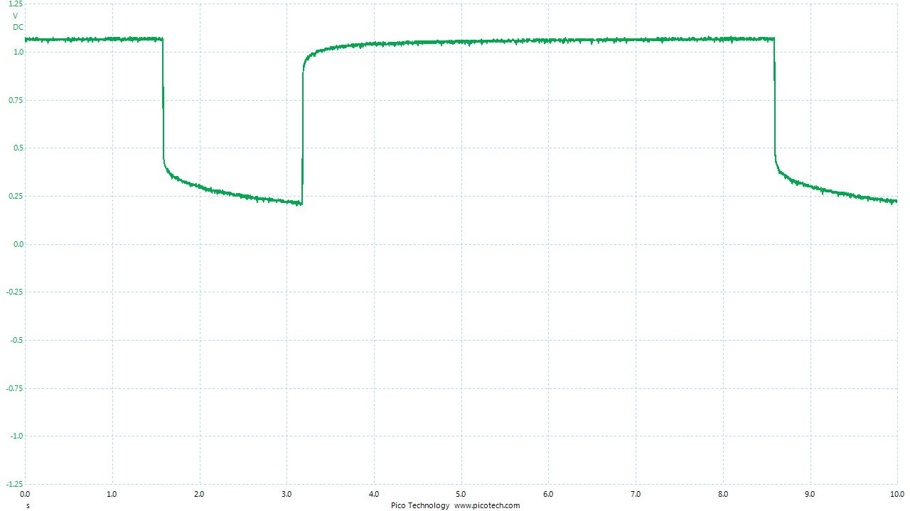
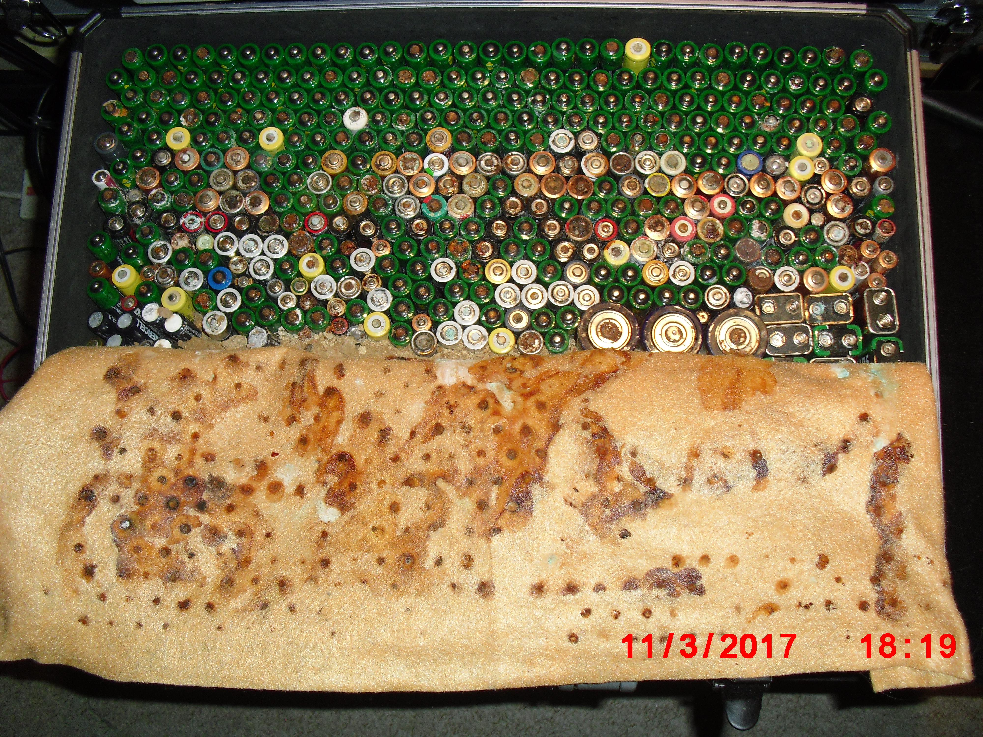
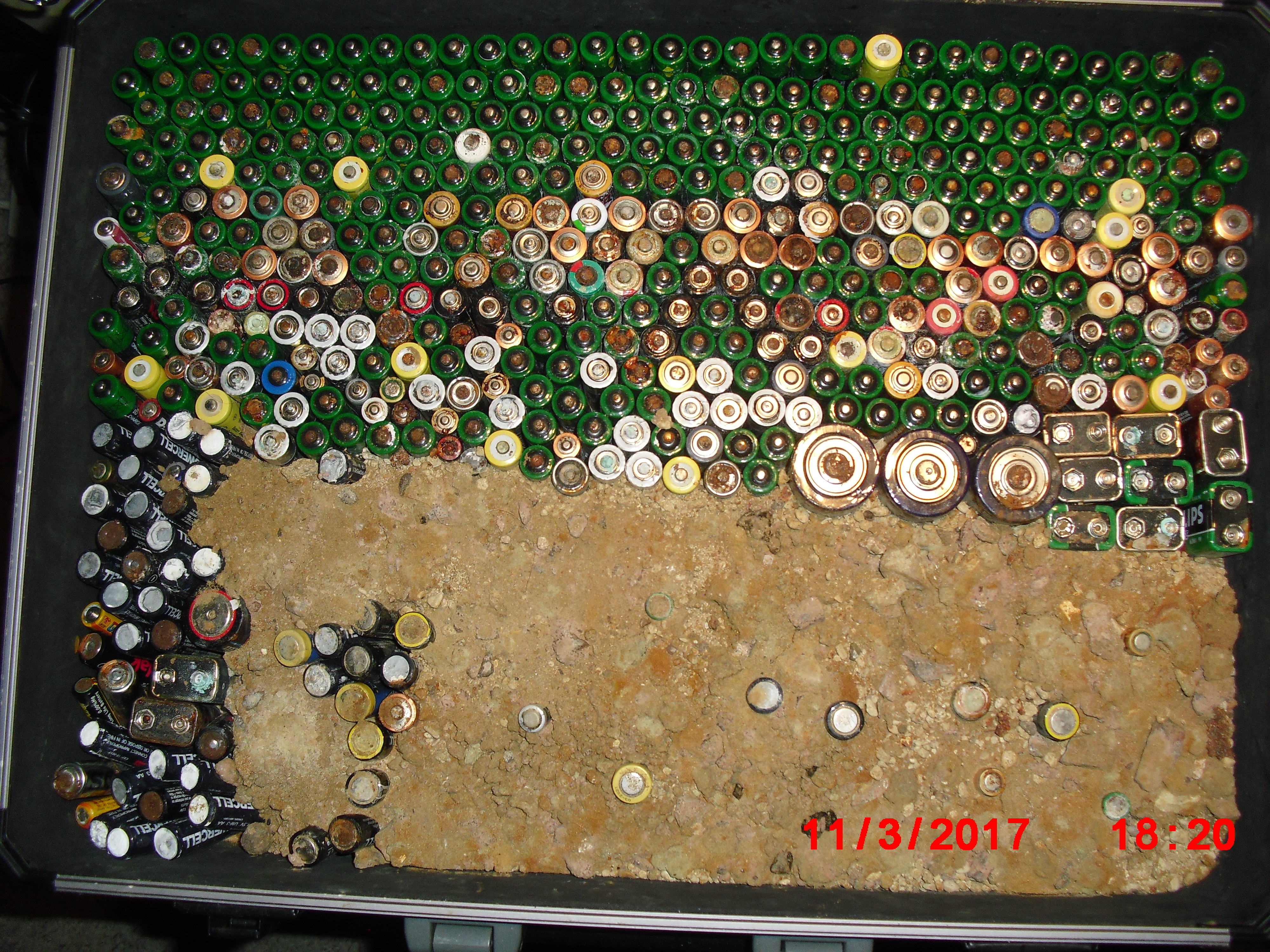
On the 8th of January 2017 I gathered together a collection of used dry cell batteries and arranged them with soil in a flight case as seen in this picture.
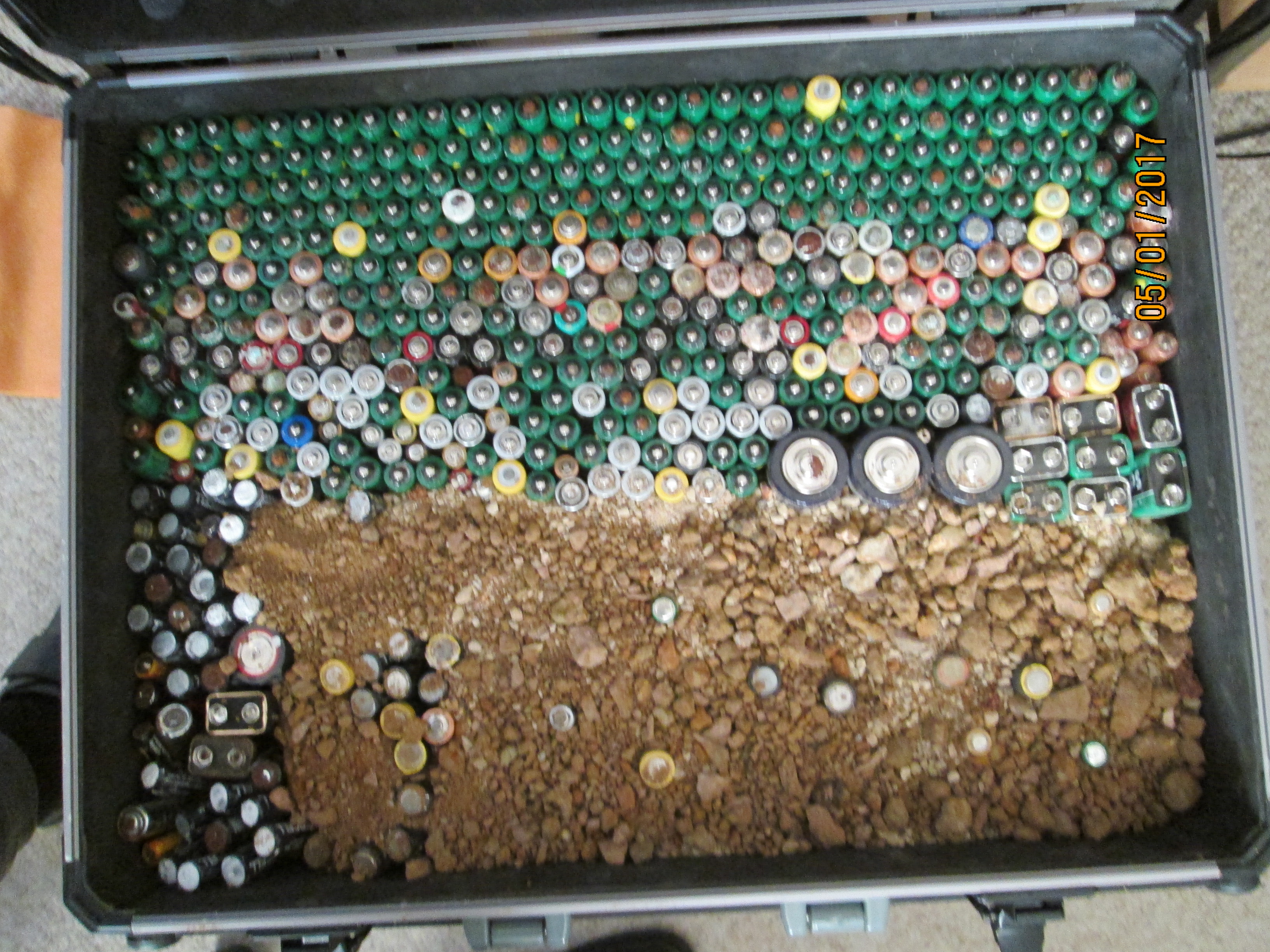
These were intended to replicate electrical conditions that I have personally found in field work in six different countries on four continents over a period of over 40 years.
It is one of the conditions that other cathodic protection specialists have described as 'teluric effects' and sometimes as 'interference'.
It is a condition that can have an effect on corrosion if the pipe is uncoated but always has an affect on the displayed values on any electrical meter. If the pipeline is well coated it will have no effect on the corrosion status but causes concern to those who do not understand what they are measuring.
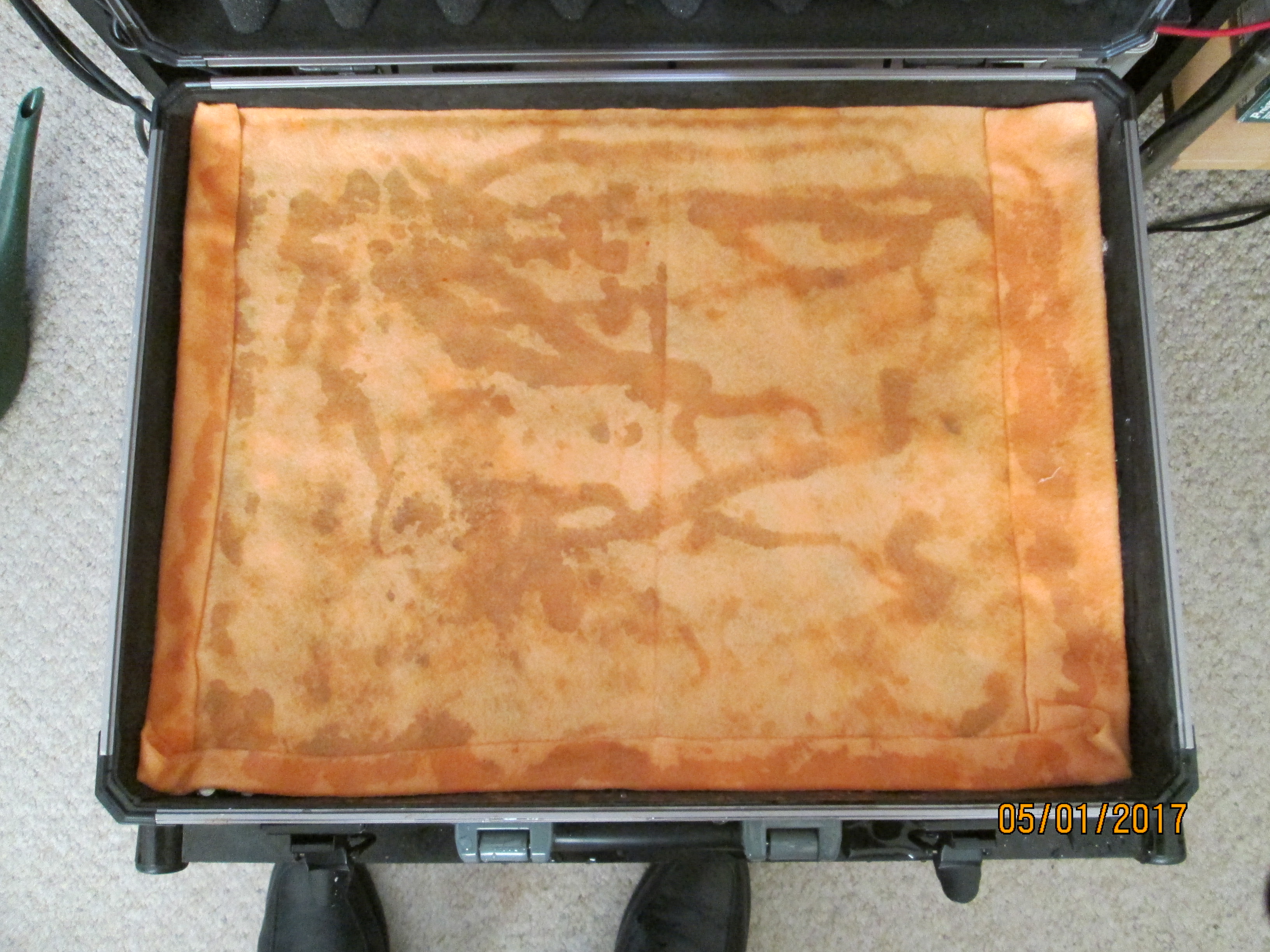
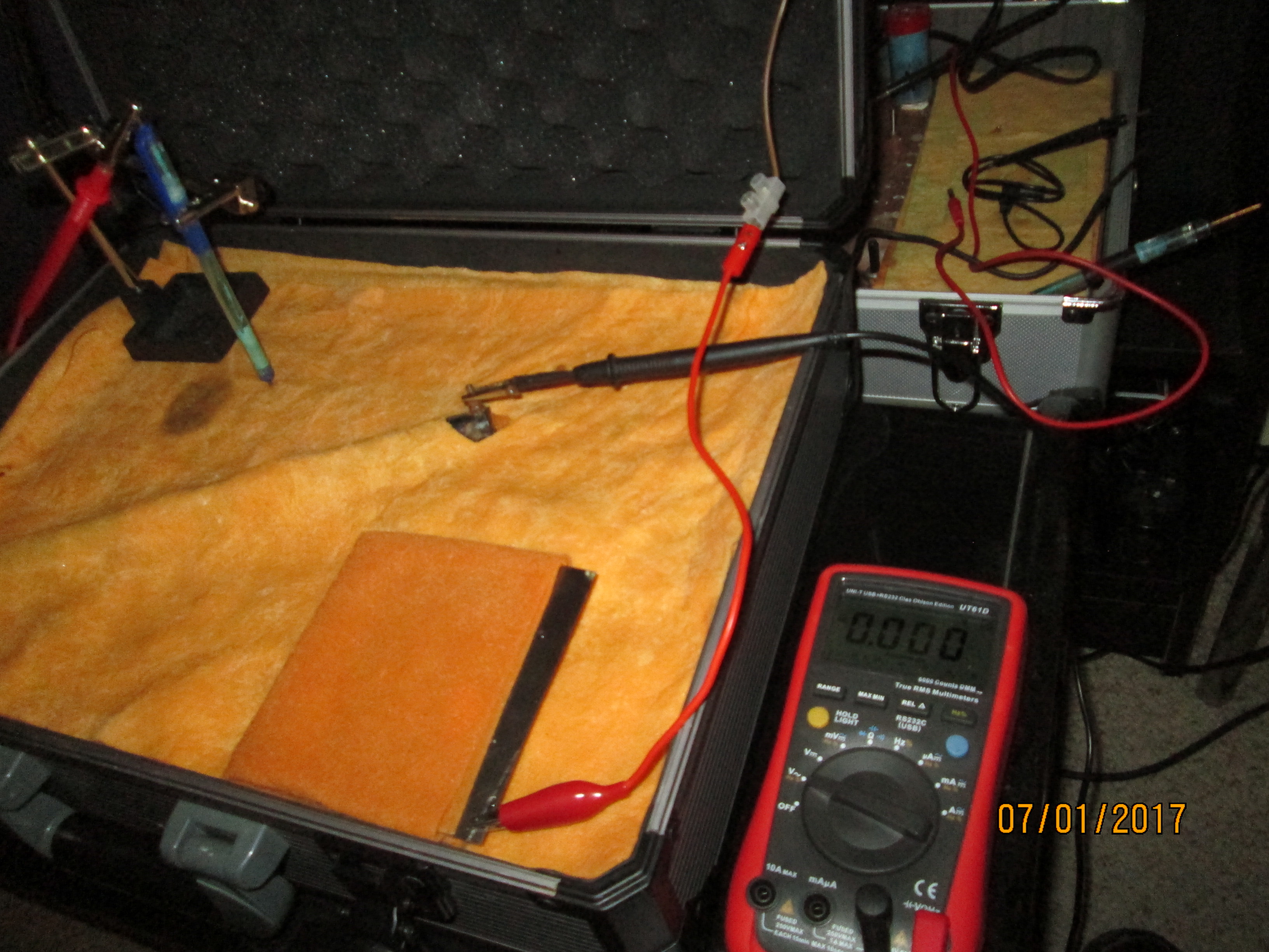
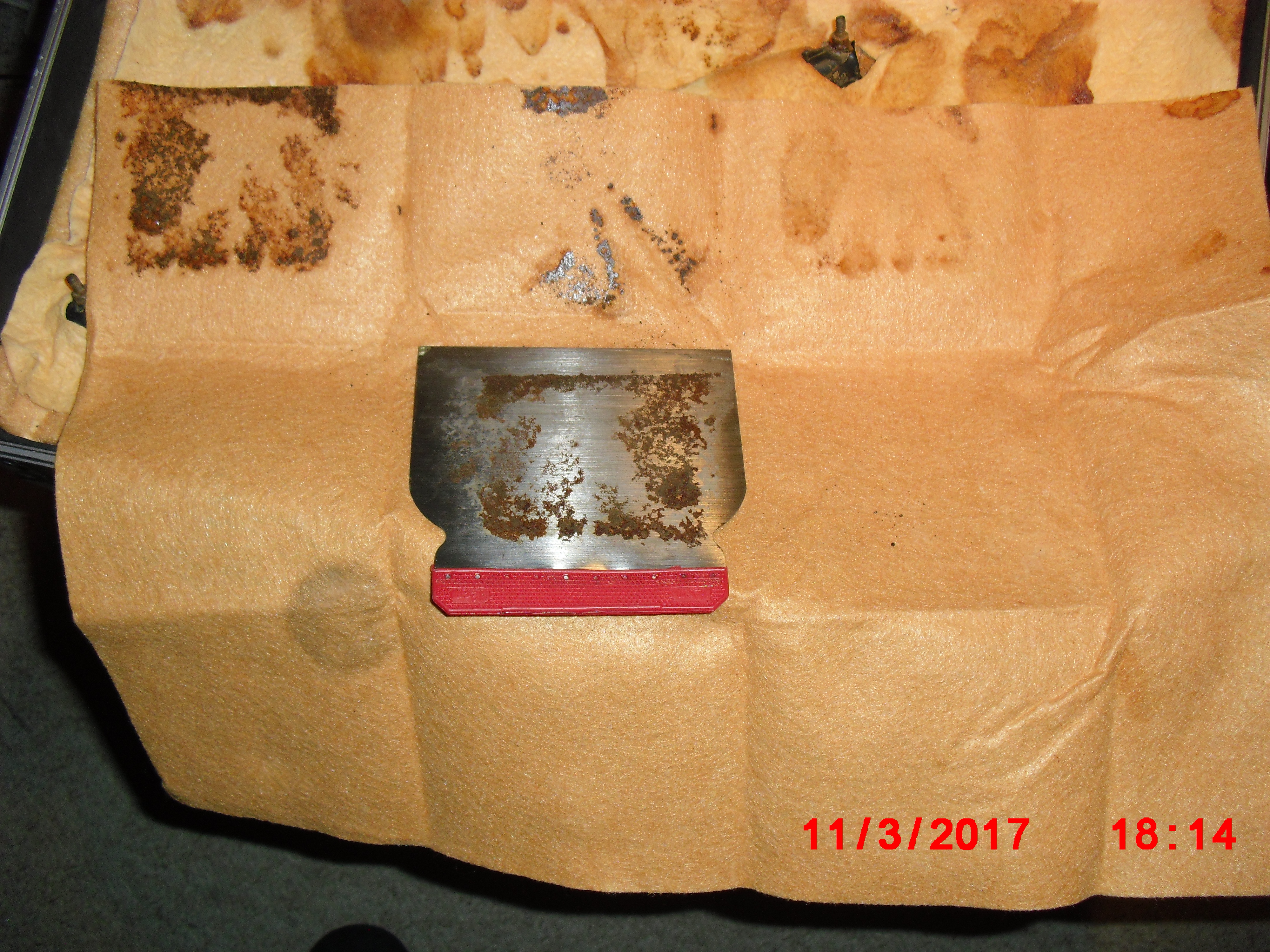
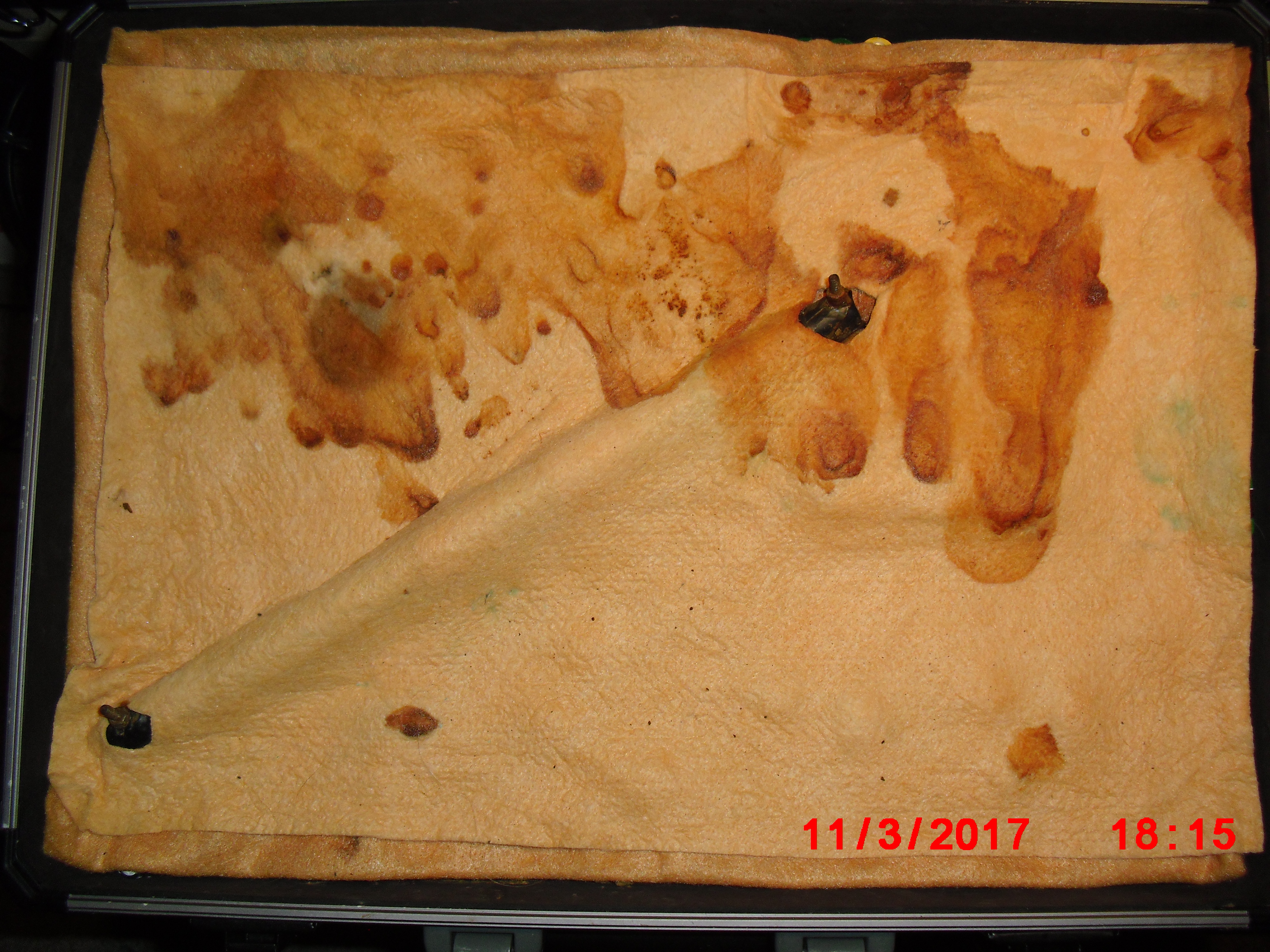
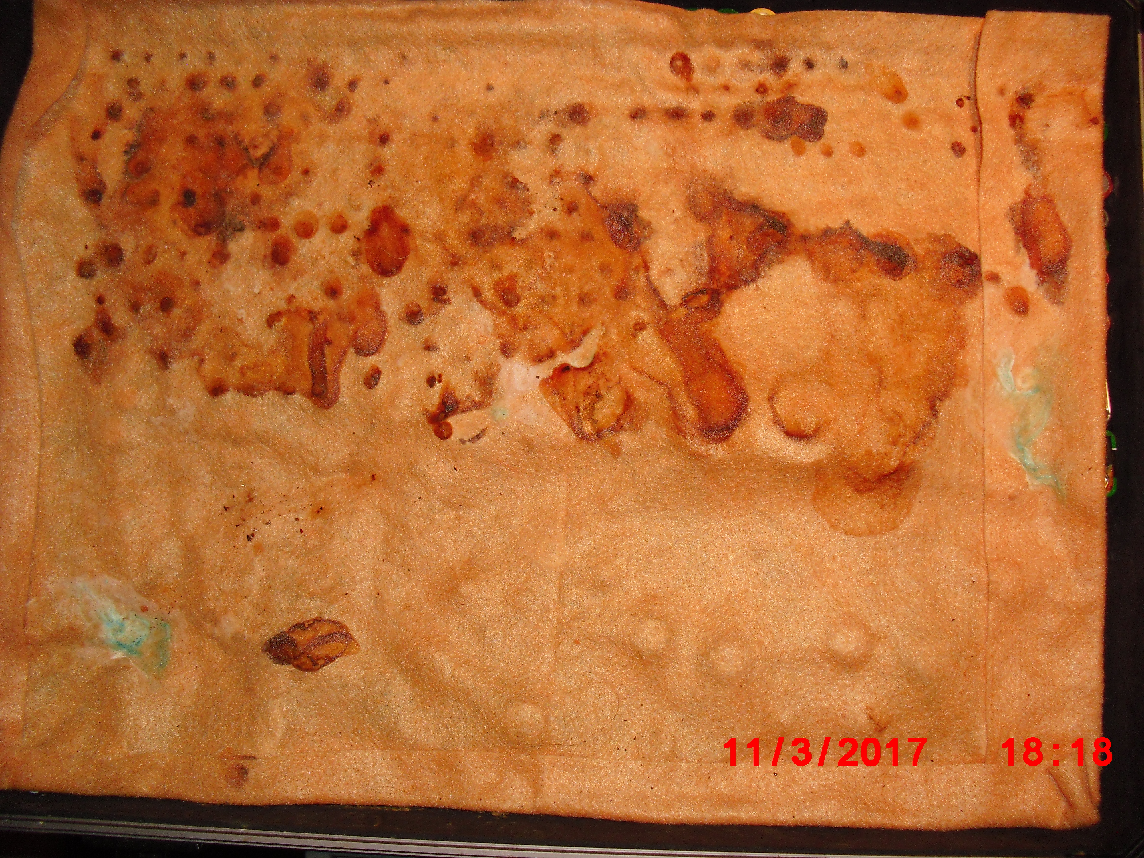
I covered the batteries and soil with damp, super absorbant cloth to represent the topsoil.
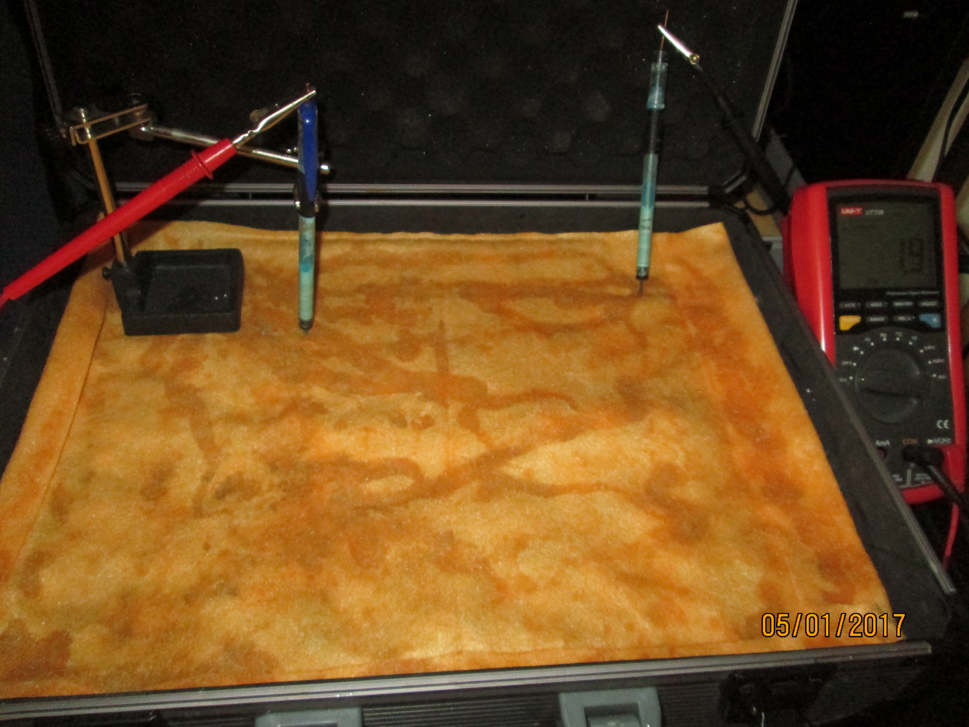
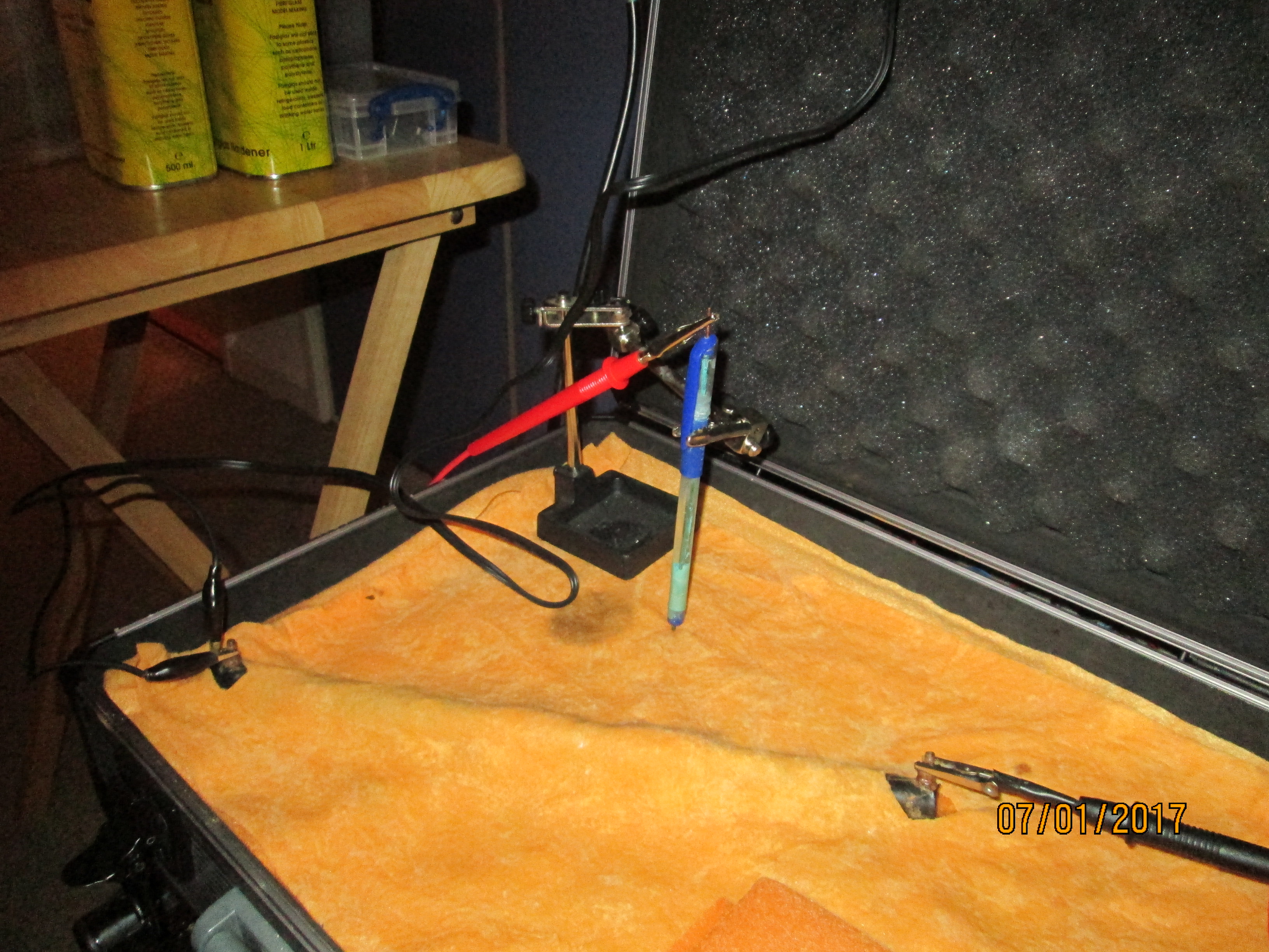
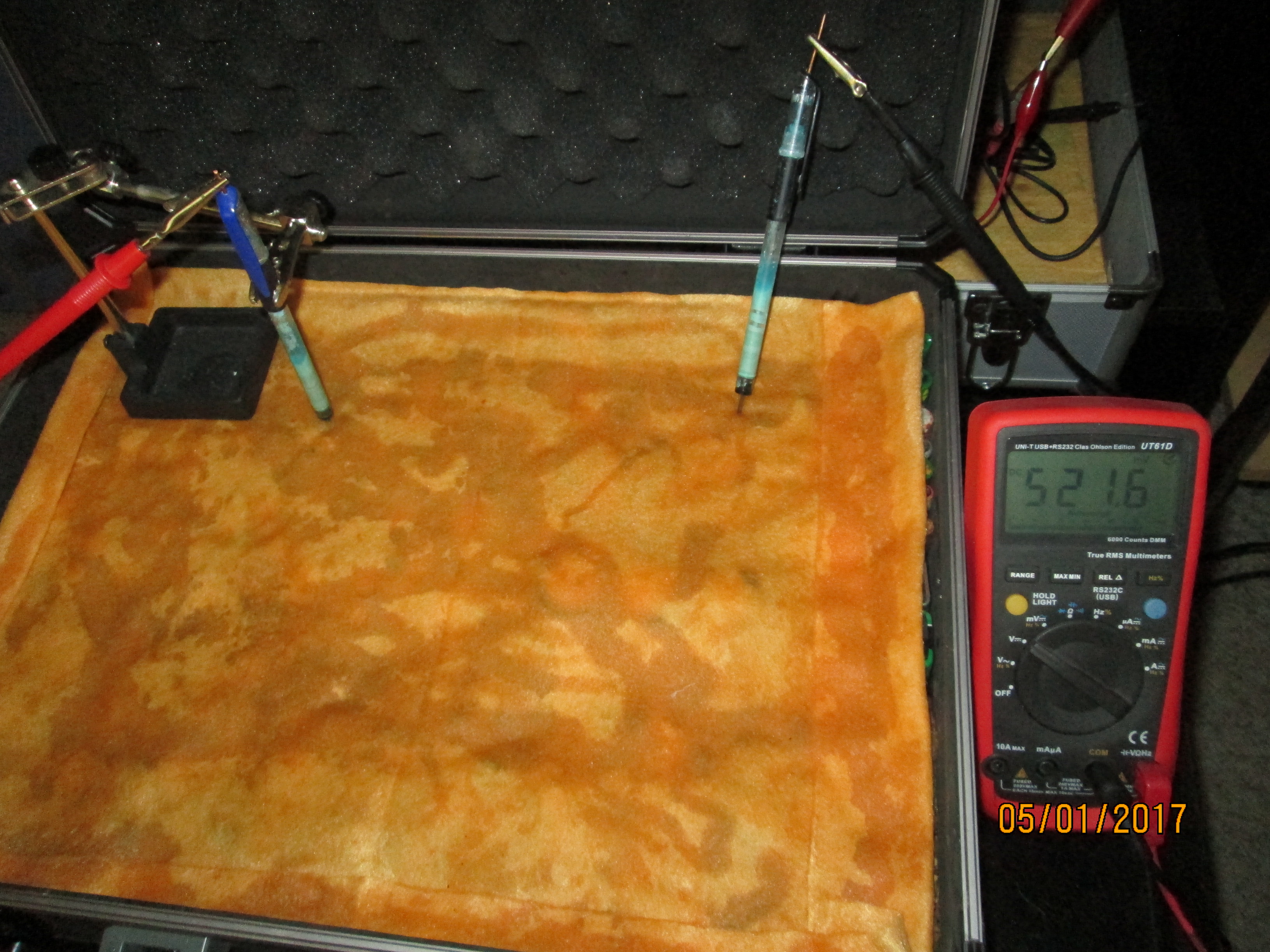
I clamped a copper/copper-sulphate electrode in a fixed position with the wooden tip touching the damp cloth, and soaked the whole of the battery bed with tap water.
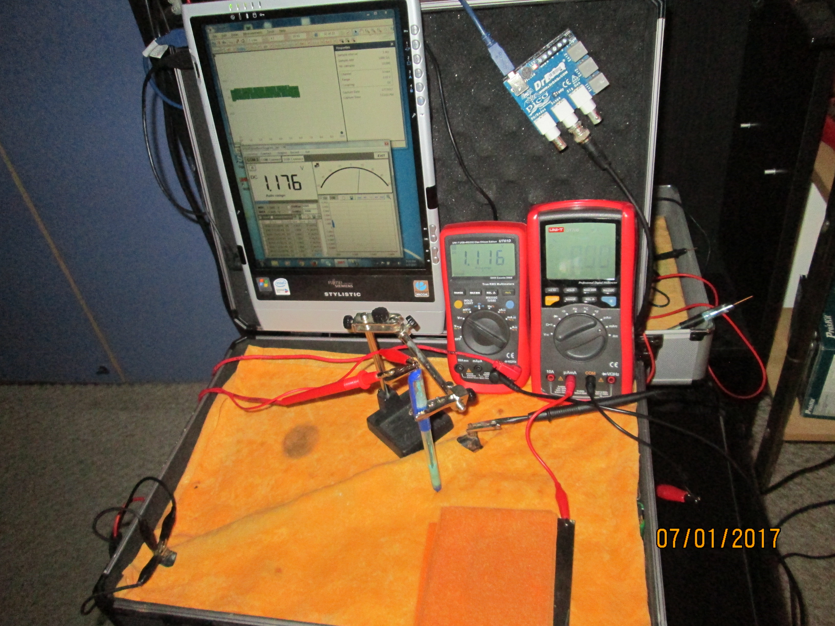
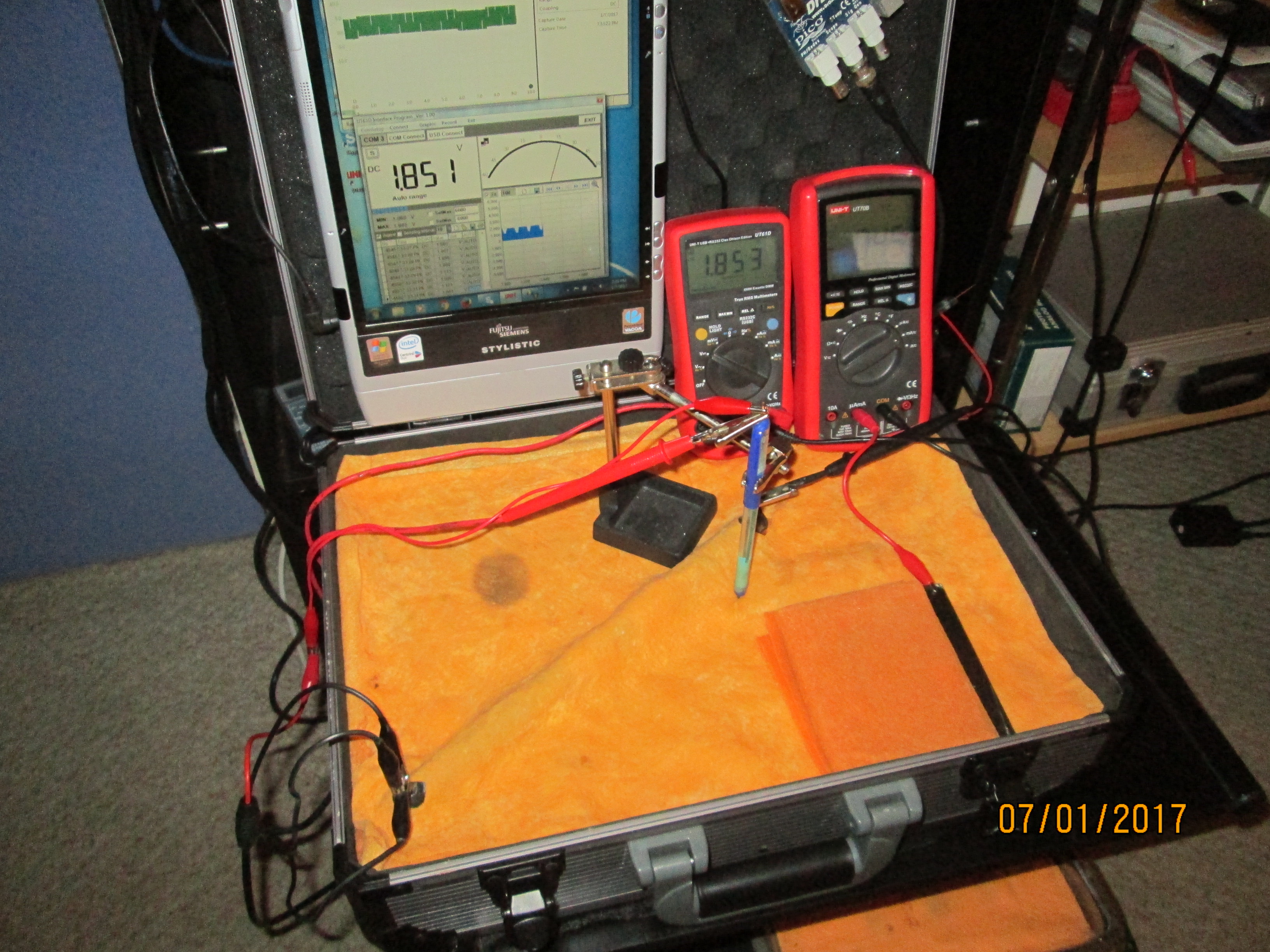
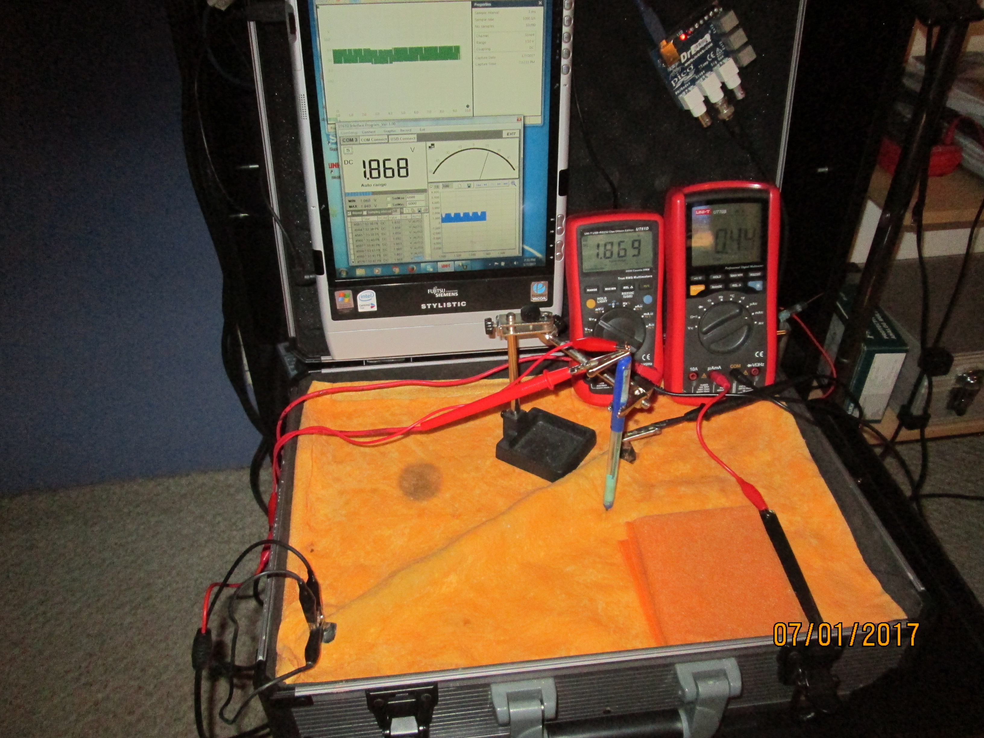
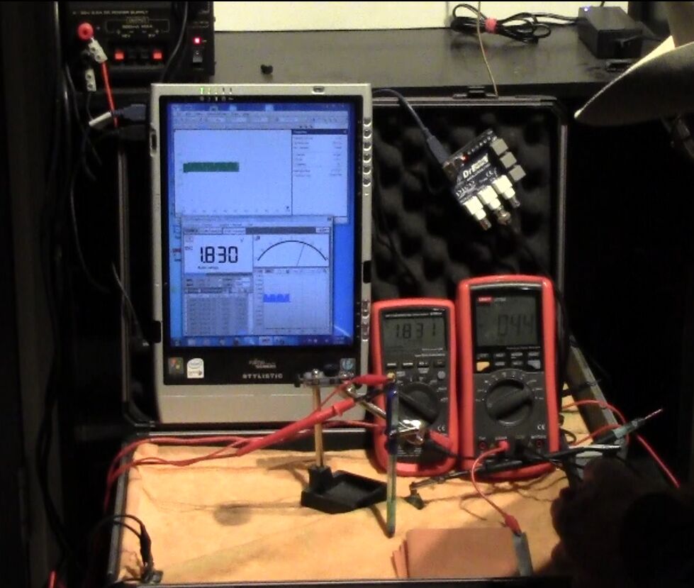
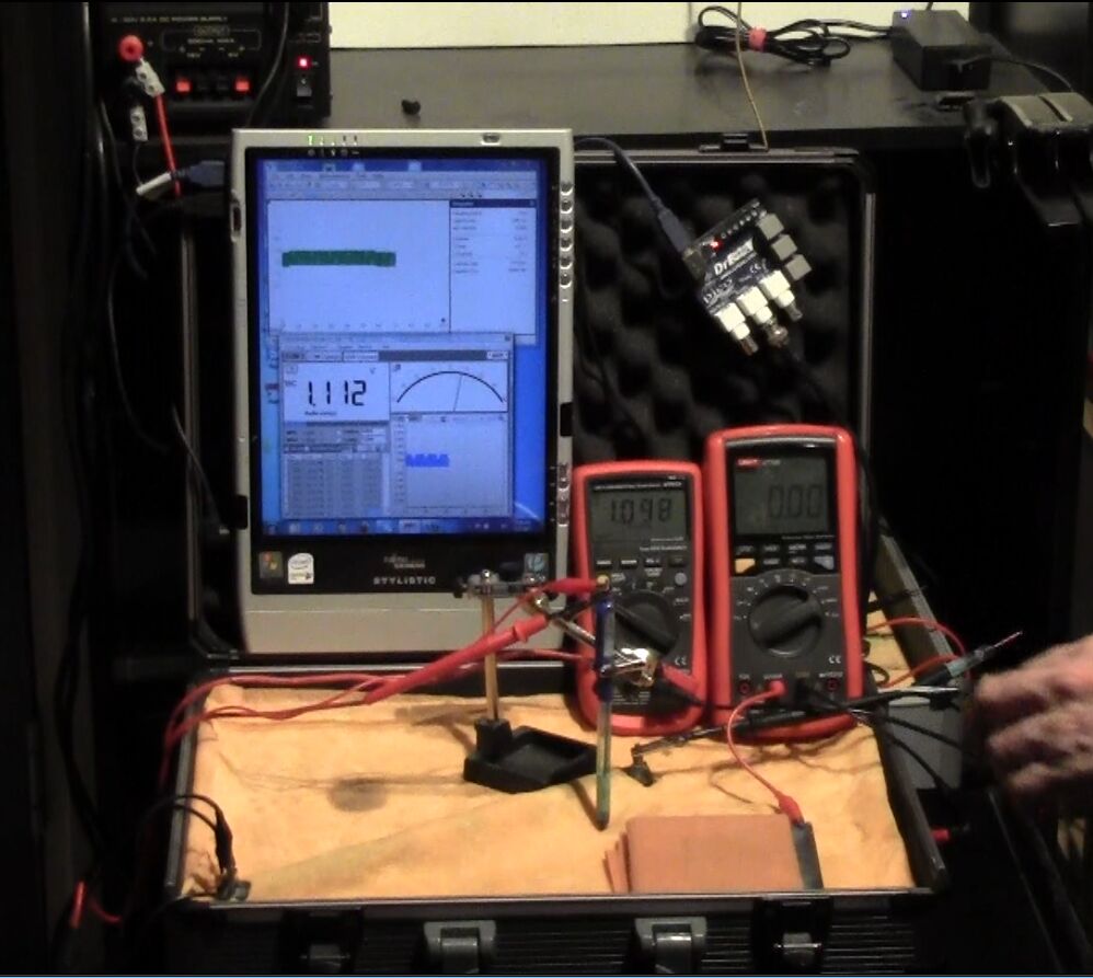
I set the UNI-T UT70B multi meter to measure volts and connected the 'common' and 'volts' terminals as seen in this picture.
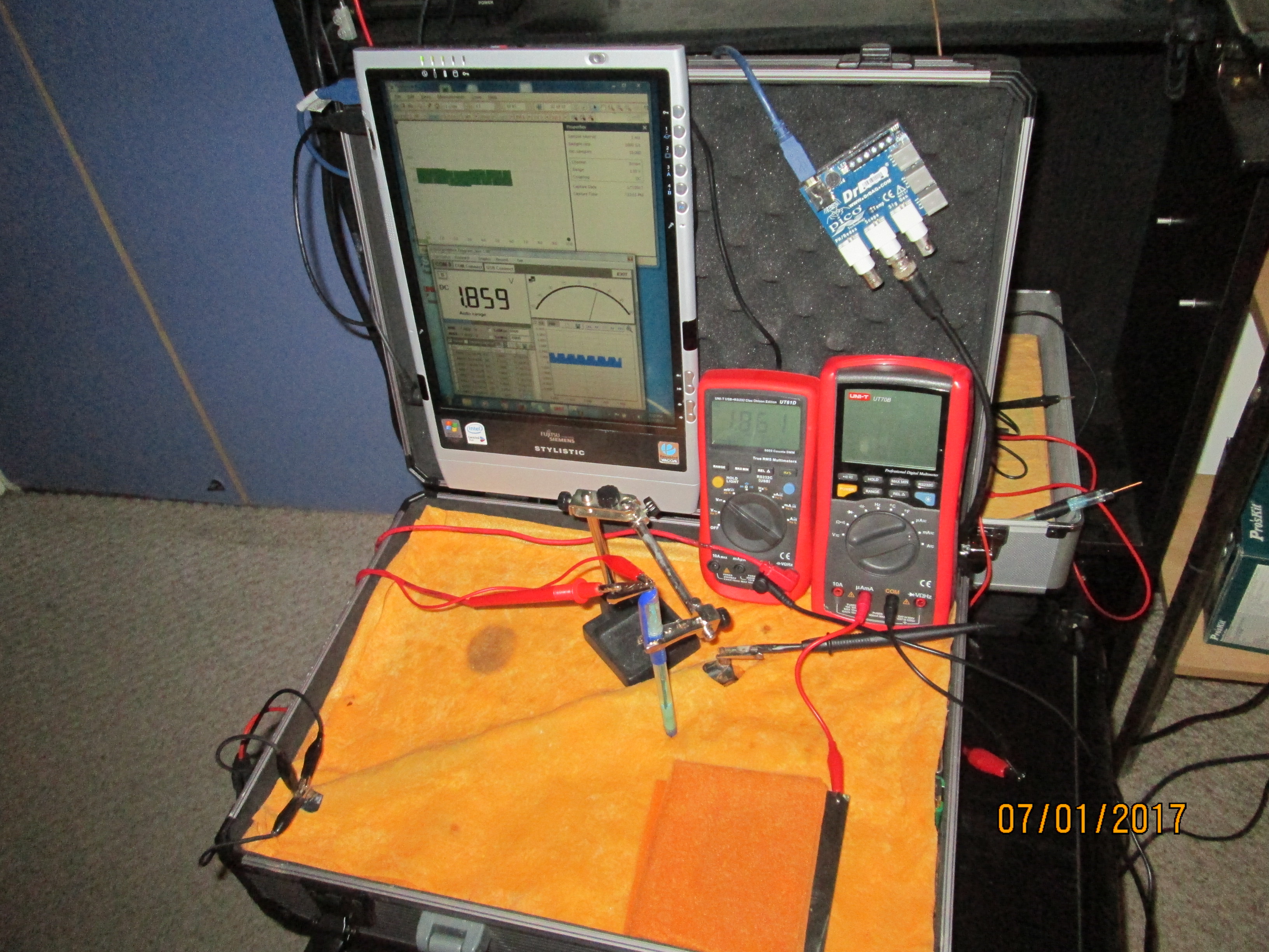
The electrical charges that were in the saturated cloth were not evenly distributed with the result that they charged up the positive and negative poles of the meter to different potentials.
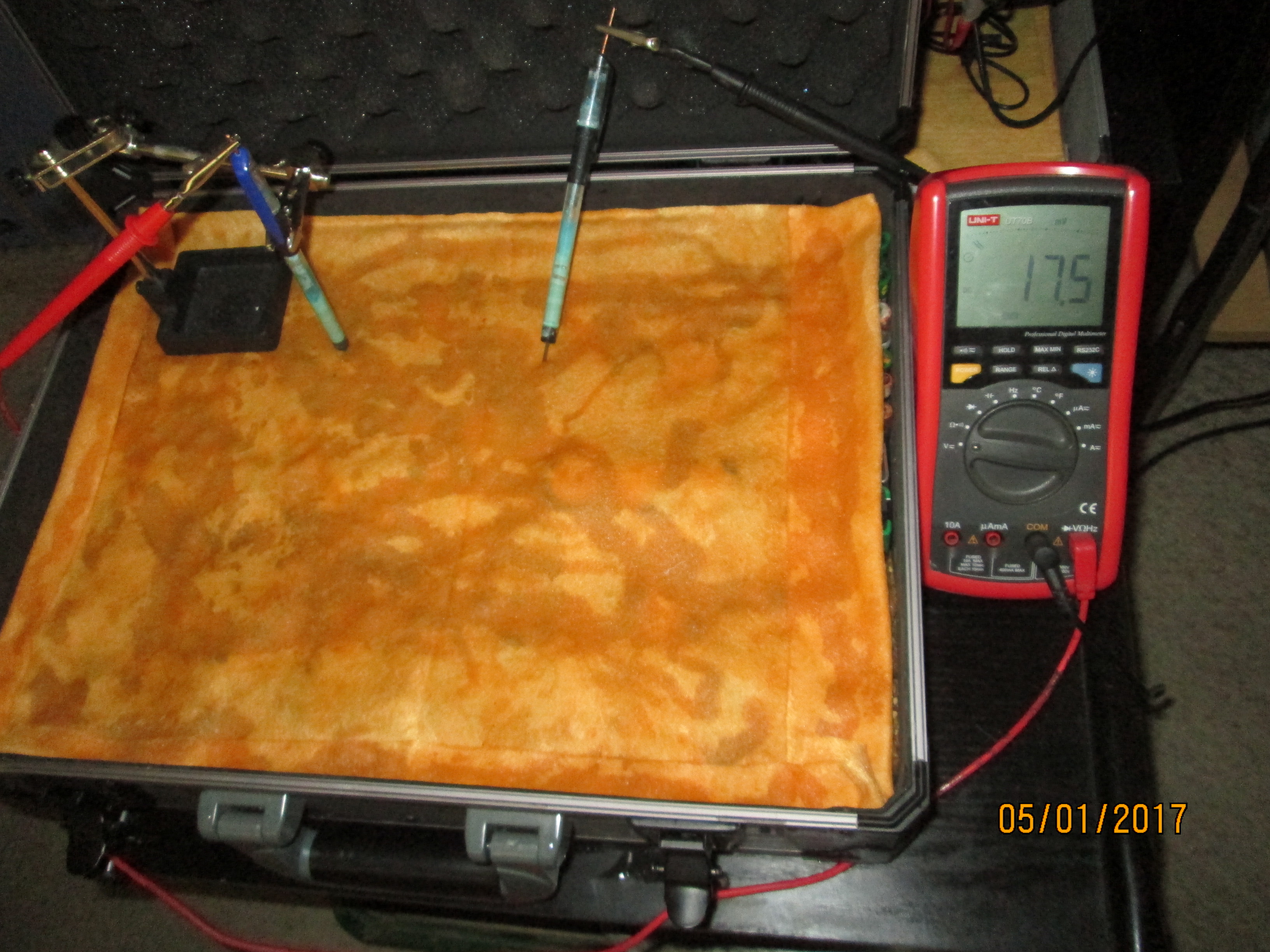
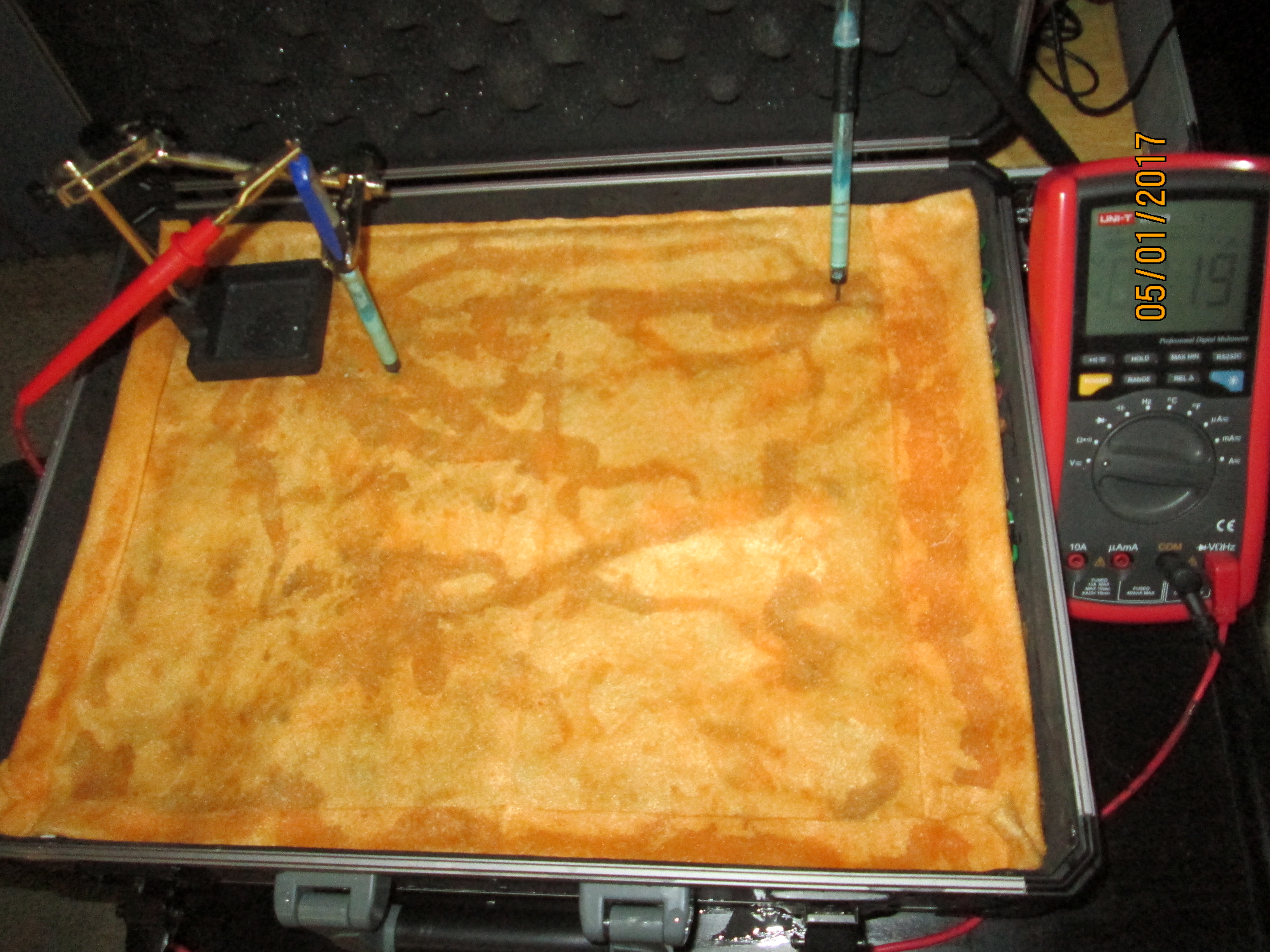
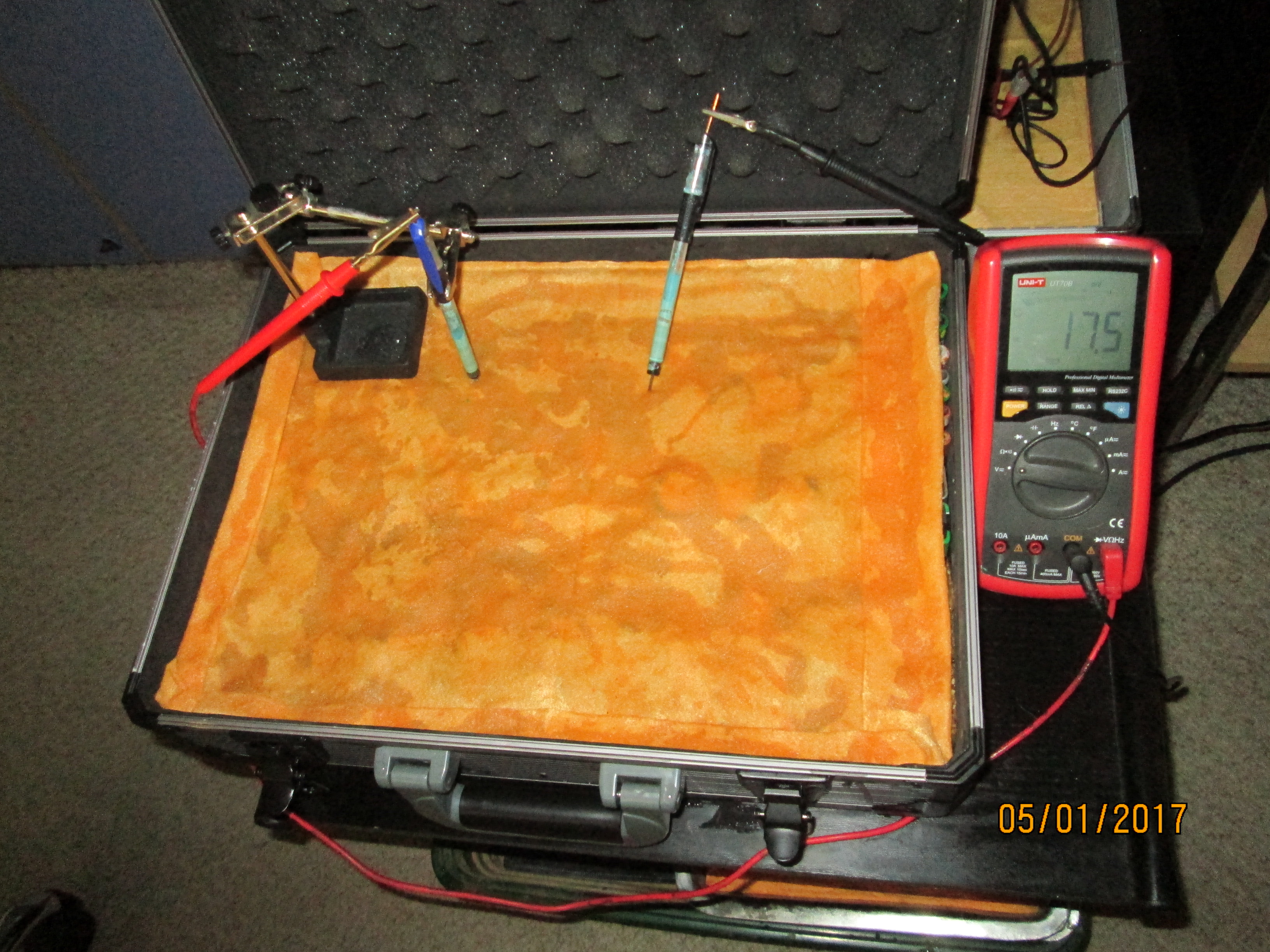
As the positions of contact were altered the displayed voltage alters.
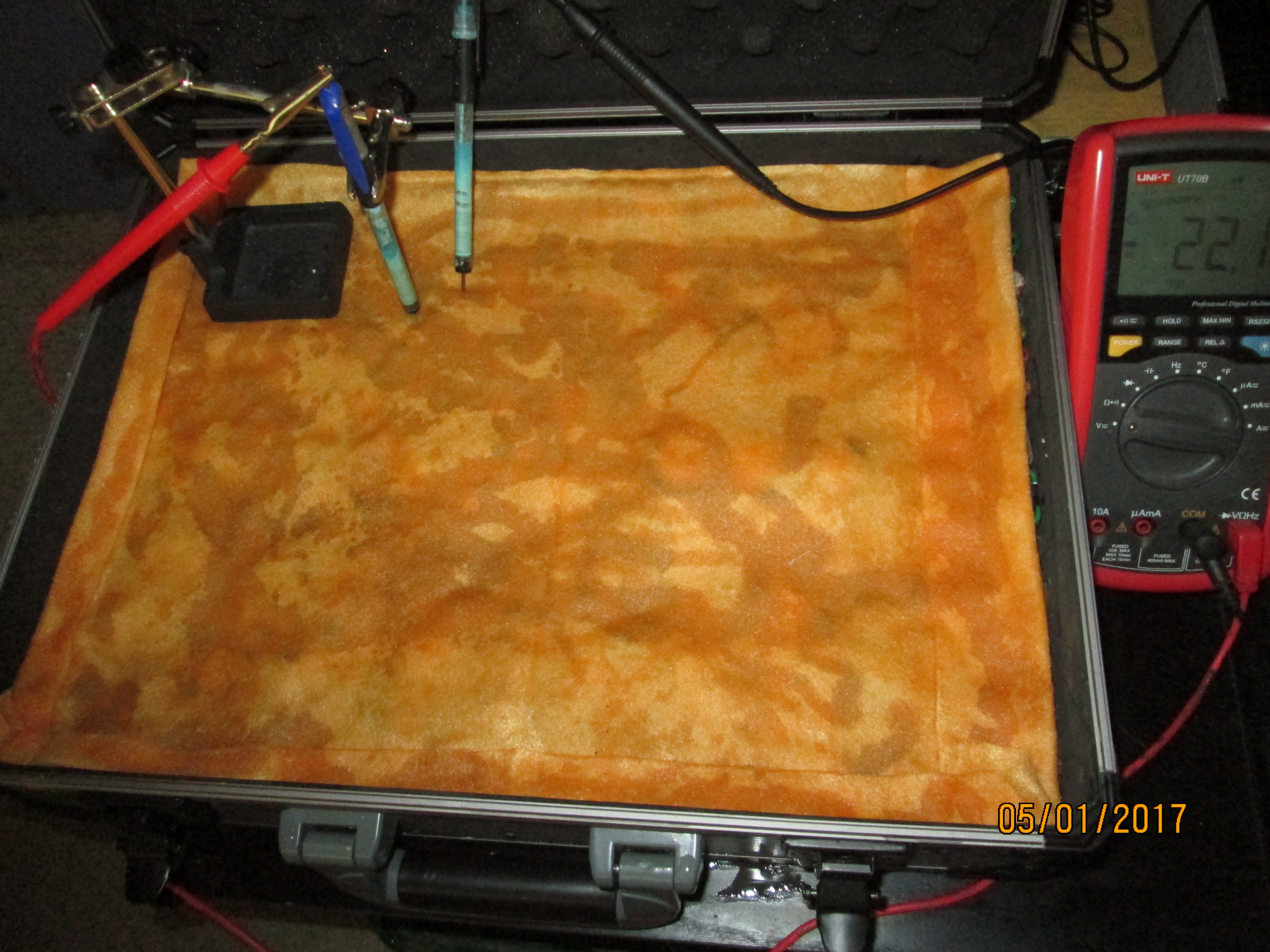
The readings change with time as the charges within the meter reach equilibrium.
In this experiment I have fixed the position of the red lead and moved the position of the black lead to show that it is the potential profile of the cloth that we are defining by this type of data acquisition. This is the principle that I applied in the mid 1970's when I invented the DCVG survey.
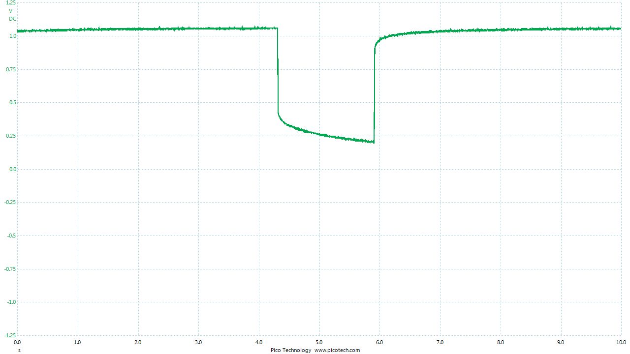
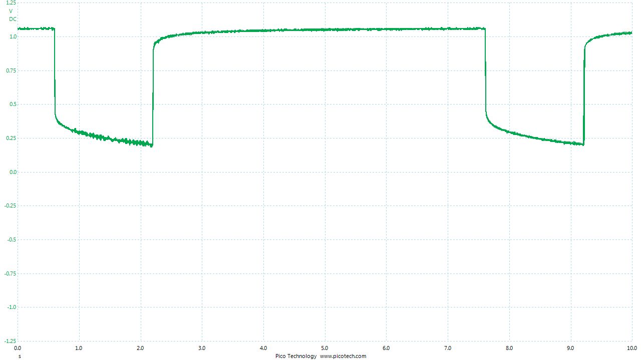
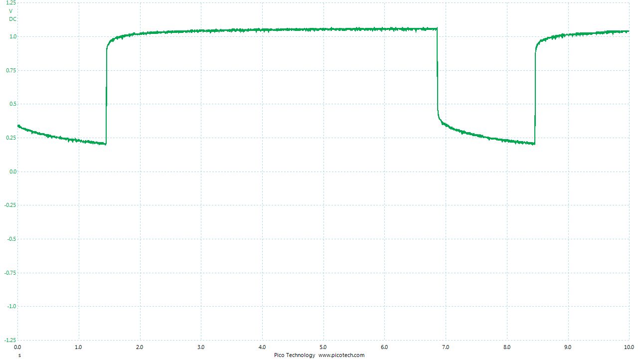
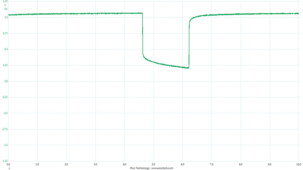
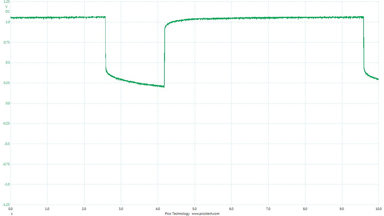
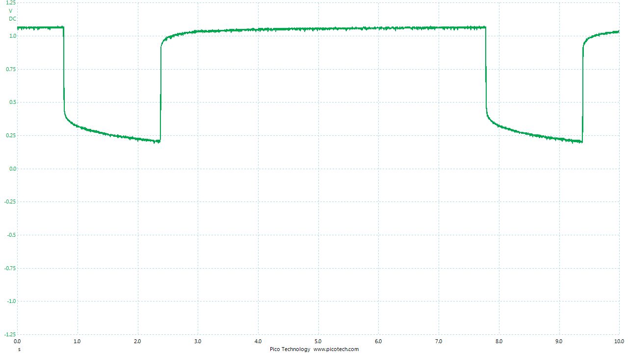
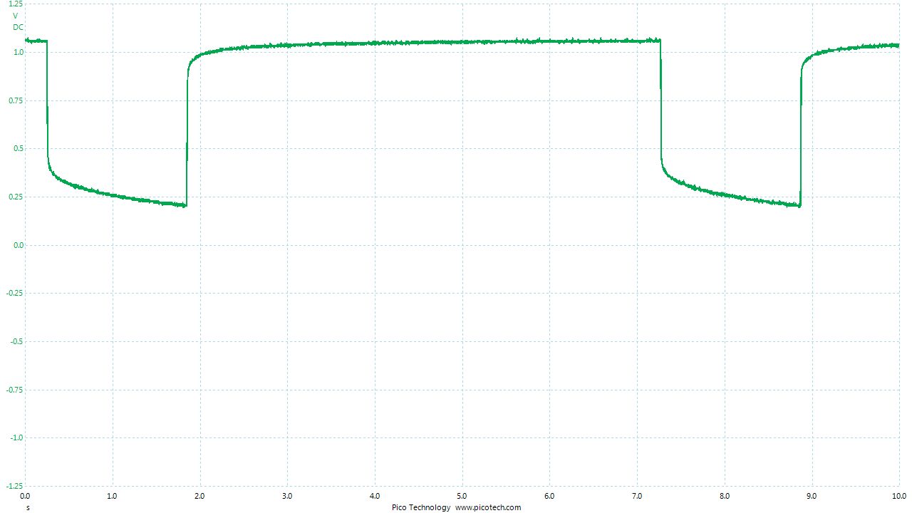
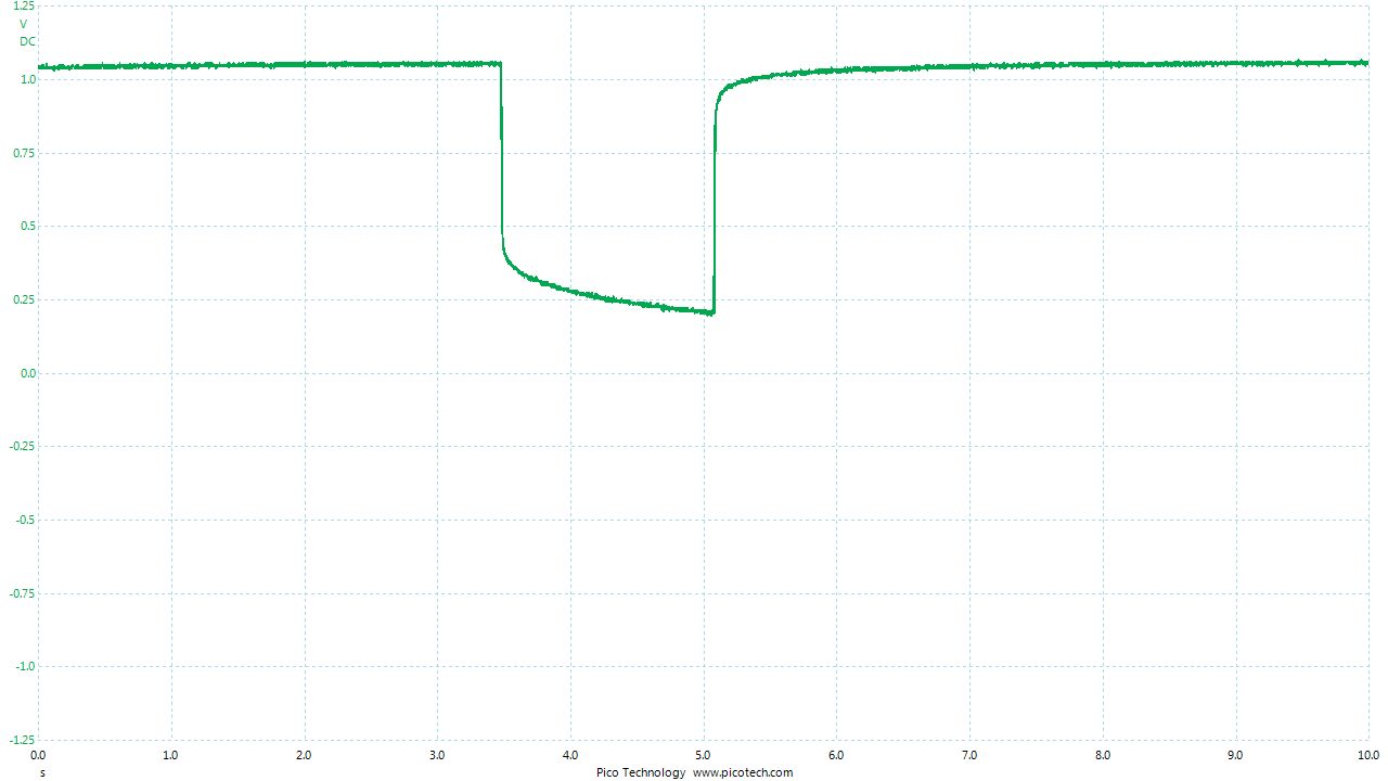
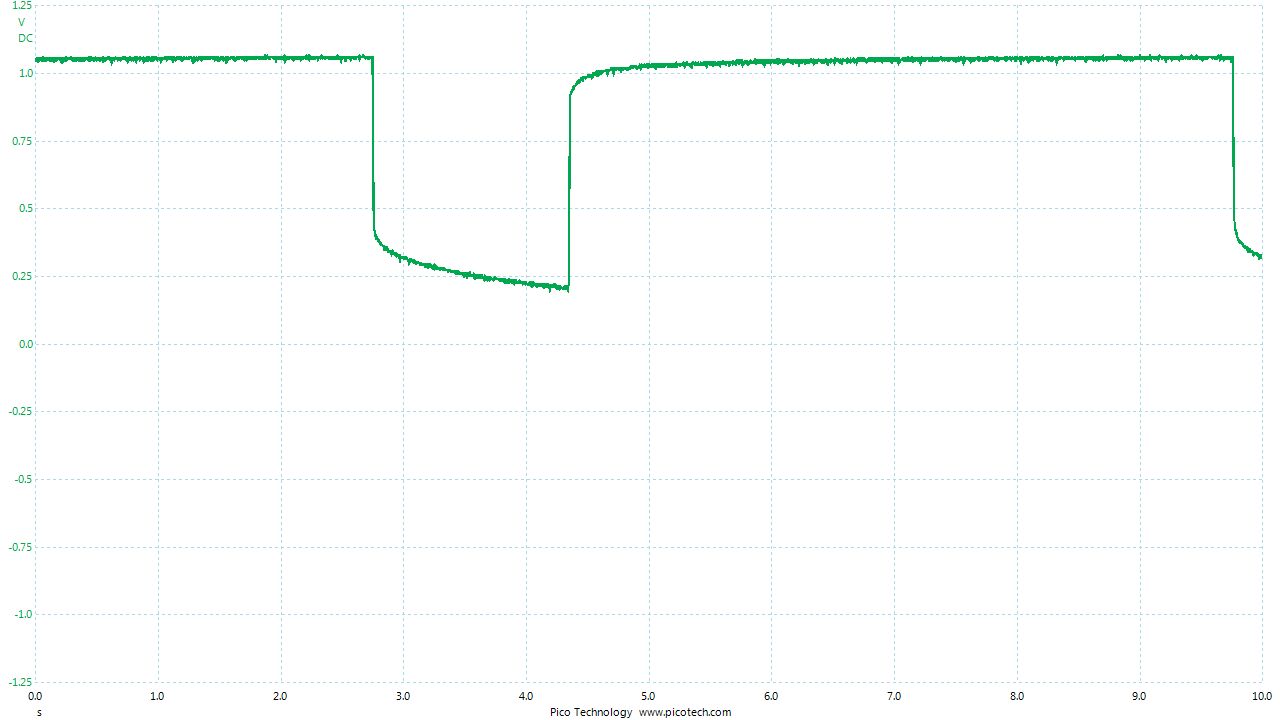
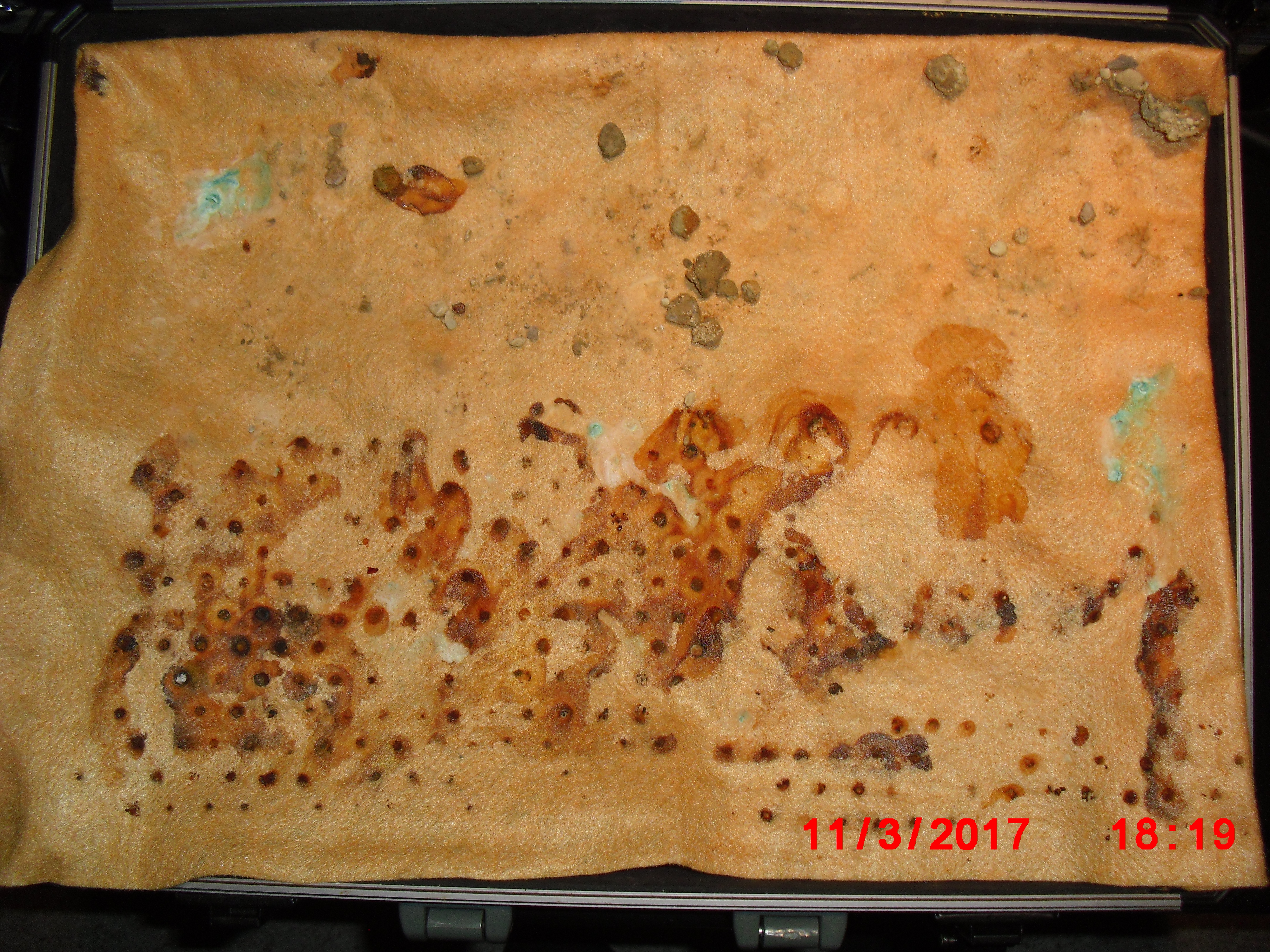
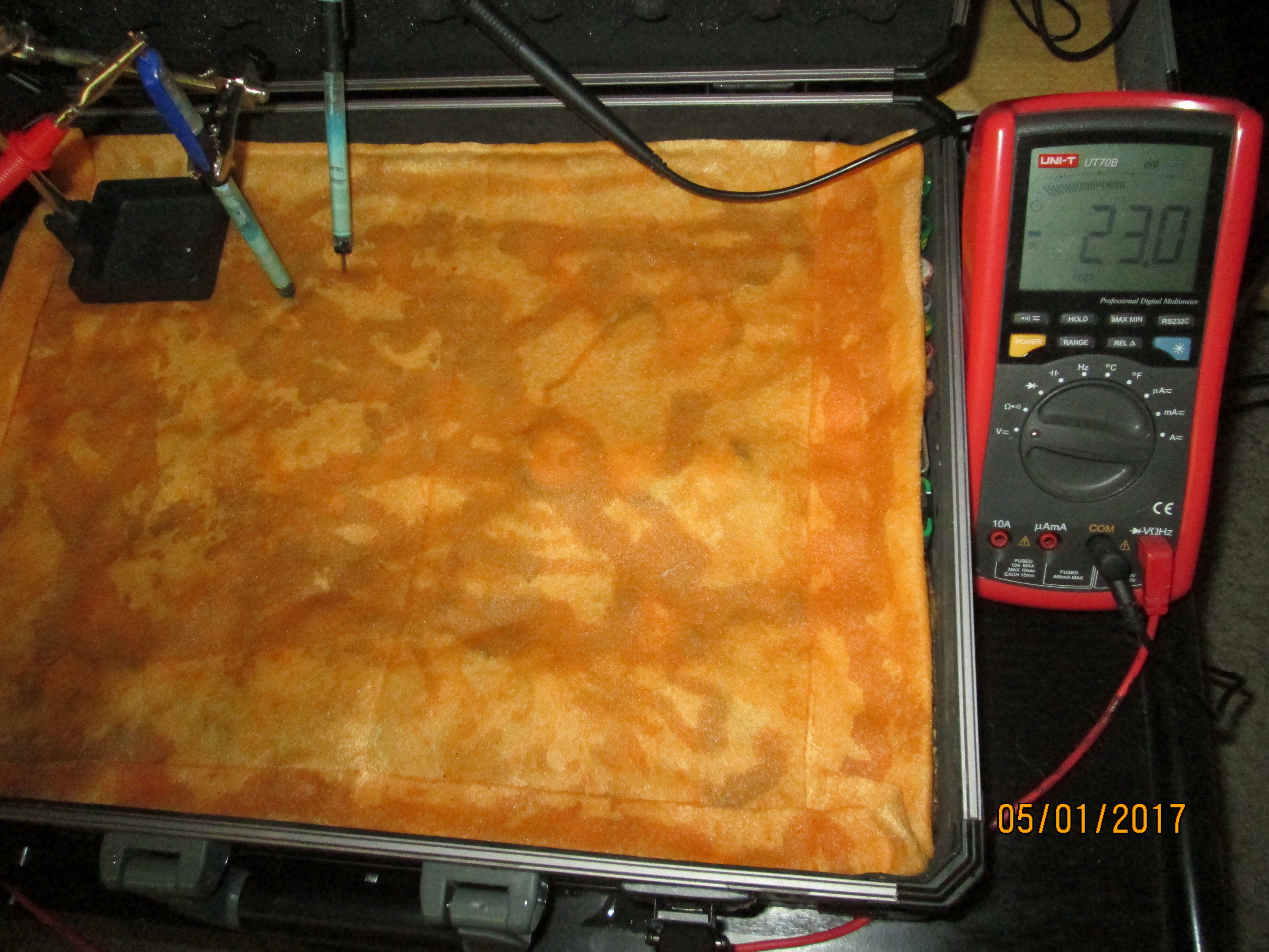
You can see in these pictures that the whole of the potential balance within the battery bed is changing in both time and space (location). The electrical structure is reaching equilibrium by reacting to the addition of the tap water.
You can see the displayed measurements are changing due to the variety of corrosion reactions in the batteries and the changing resistances in the paths taken between the terminals of the meter.
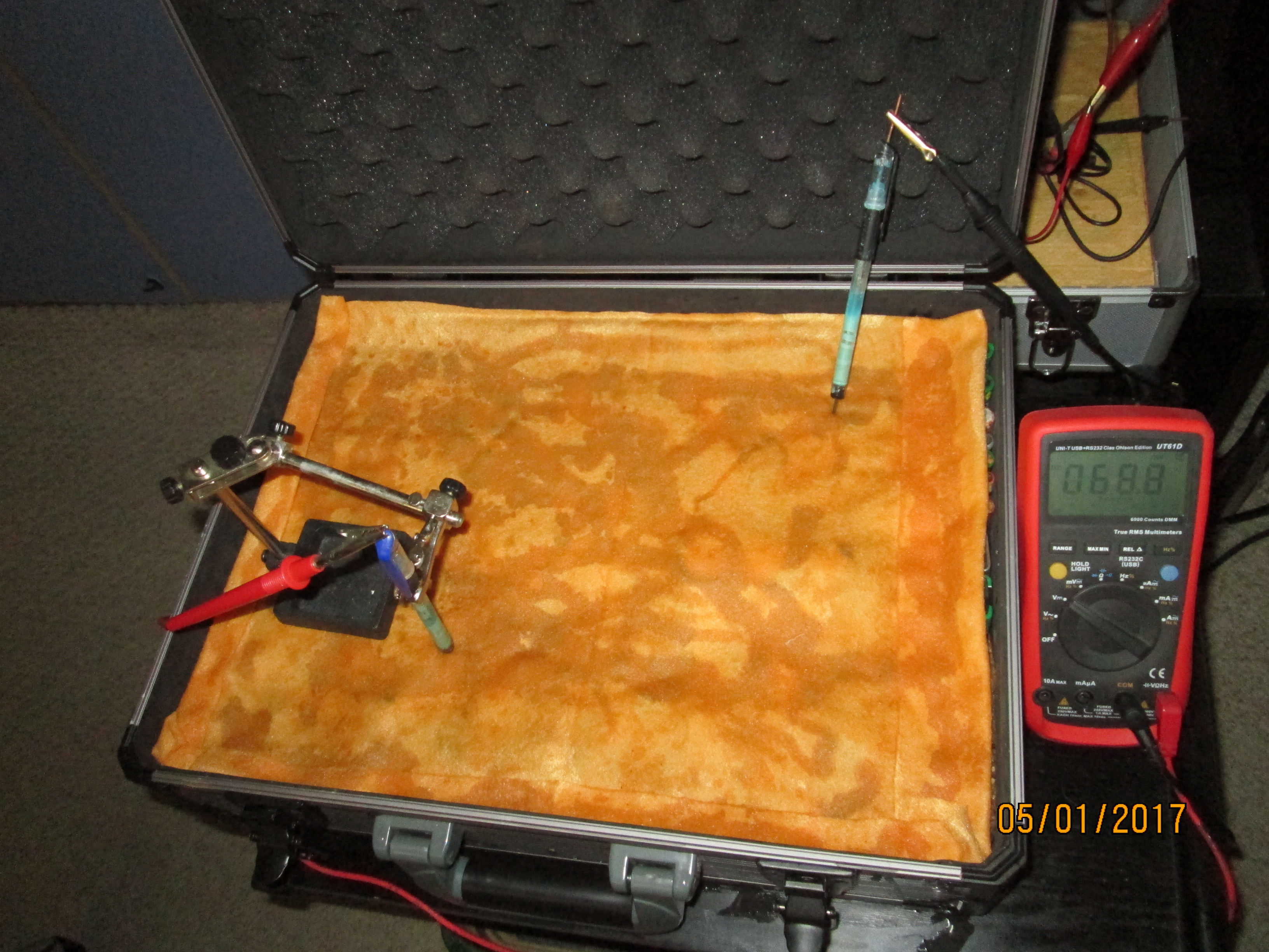
When we add water in the process of carrying out DCVG or CIPS surveys we alter the electrical structure of the measuring circuit and this can be observed in this experiment.

I gathered some copper/copper-sulphate electrodes that I had used in other experiments and tested the meter by resting the crocodile clips on the cloth to check that there was a voltage.
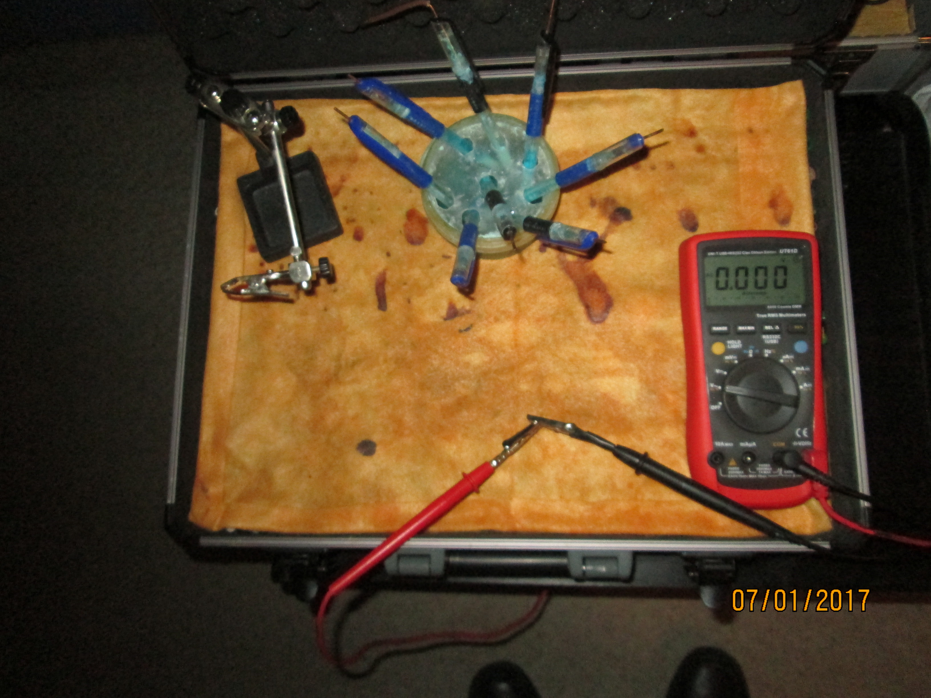
I checked the meter to zero by connecting the two clips together.
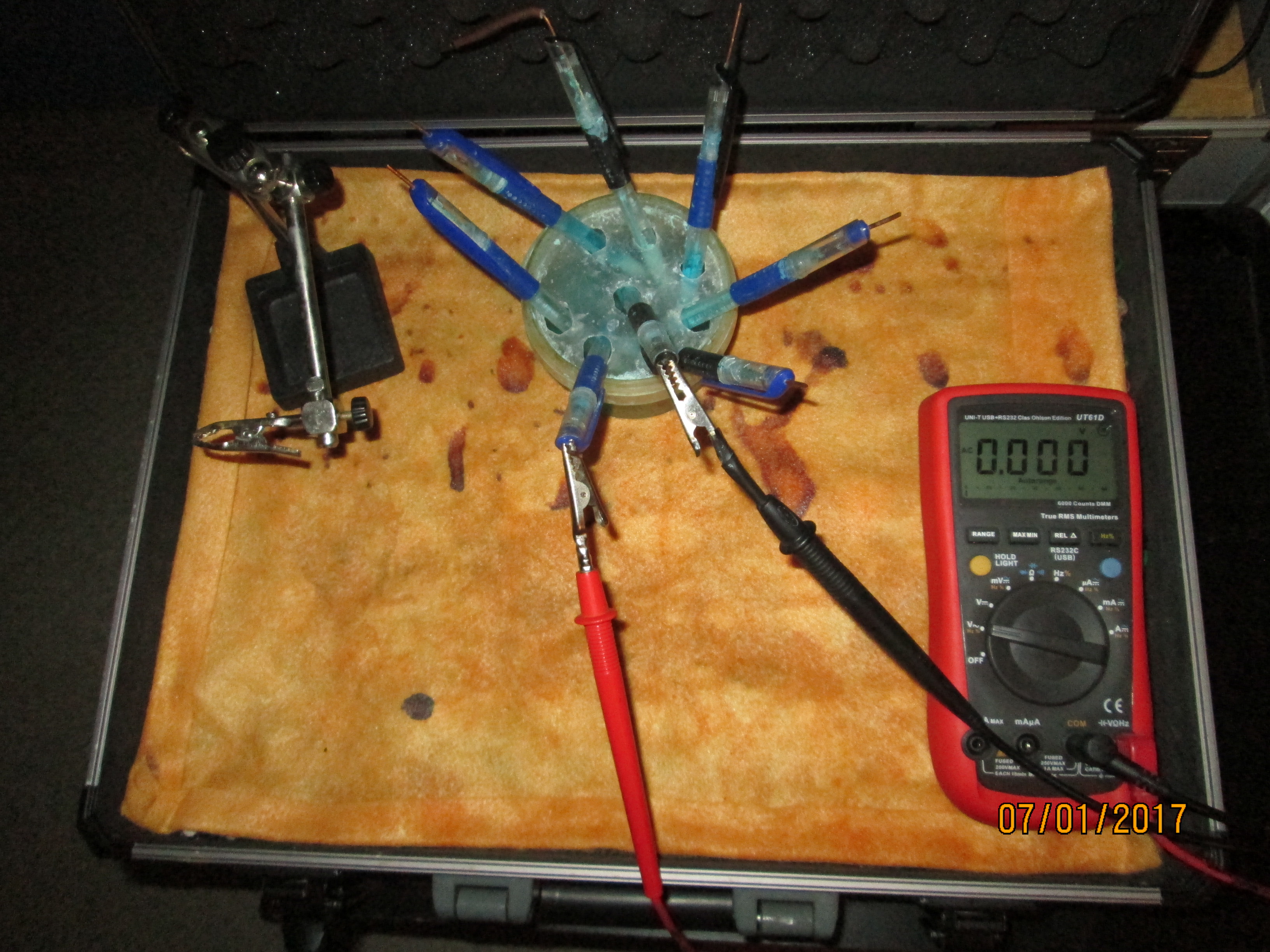
I refreshed the copper/copper-sulphate electrodes with distilled water and measured the voltage between each.
Each copper/copper-sulphate electrode has a wooden tip that is in a ssaturated solution of copper sulphate in the container in which they are stored.
As you can see in each picture, the voltages between each are within the accepted limits of this test that is recommended by the manufacturers of such electrodes and scientists.
The copper core in each electrode is made of conductor wire that has a very critical specification of purity.
The copper sulphate crystals are copper 11 sulphate assay 99.5%
The water is to CC DIW005 standard as supplied for battery top-up to be used in lead acid batteries in which it dilutes concentrated sulphuric acid as it does in this present use.
The measurement that we are making in this case is an 'impact reaction' and not an equilibrium measurement.
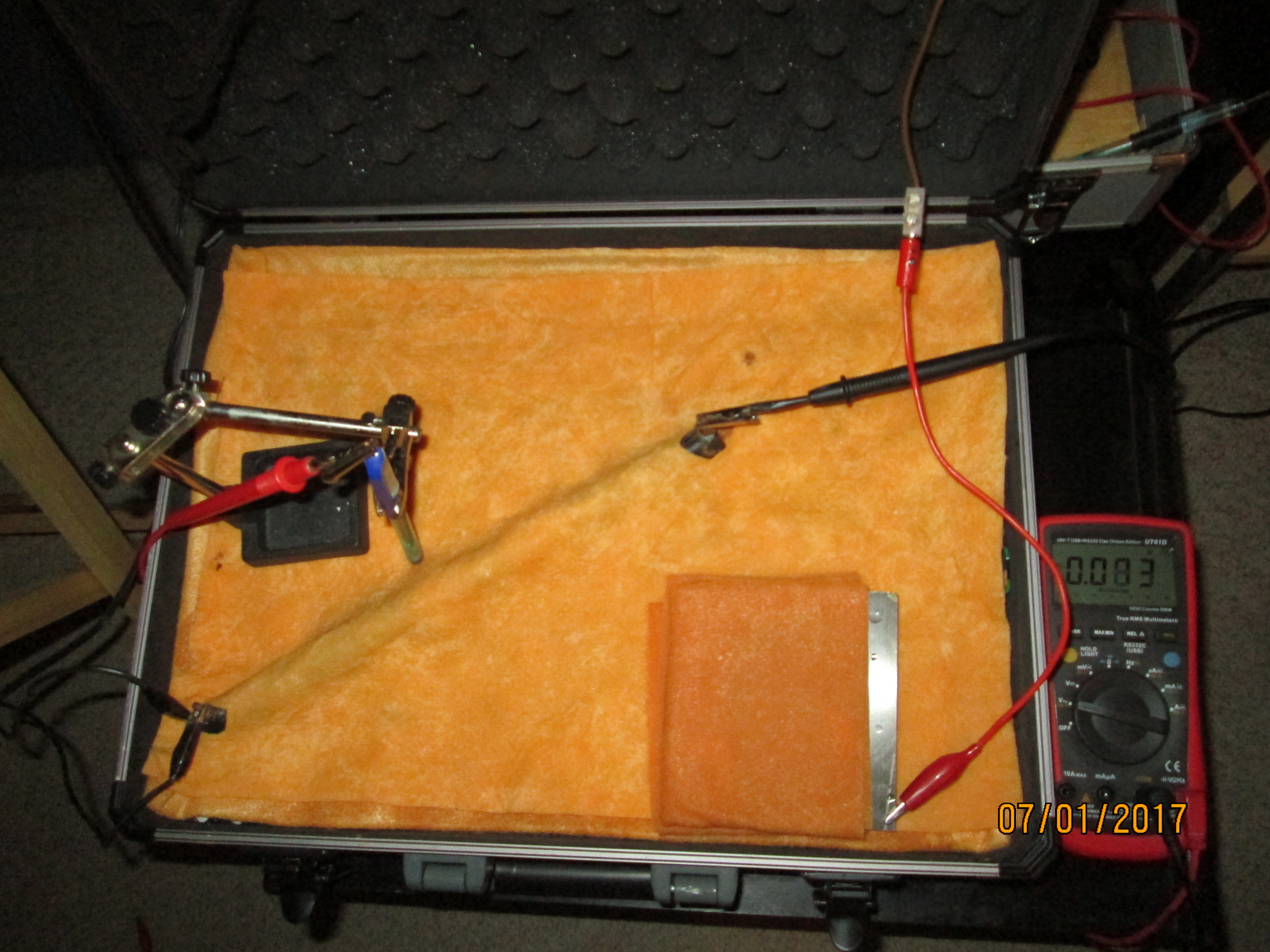
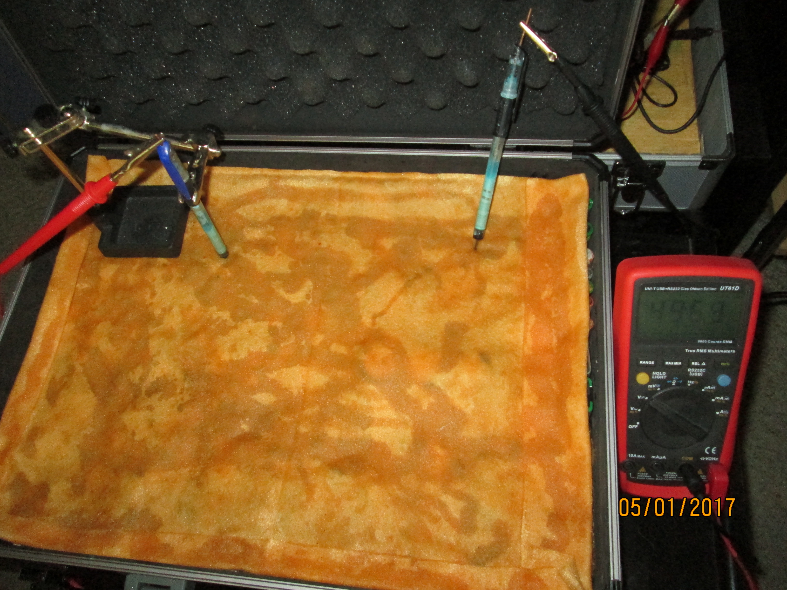
We can now use two copper/copper-sulphate electrodes to measure voltages in the damp cloth/soil.
By probing the discoloration of the cloth it produces only 2mv
Adding tap water does not increase the voltage displayed.
Moving the right hand electrode increases the voltage.
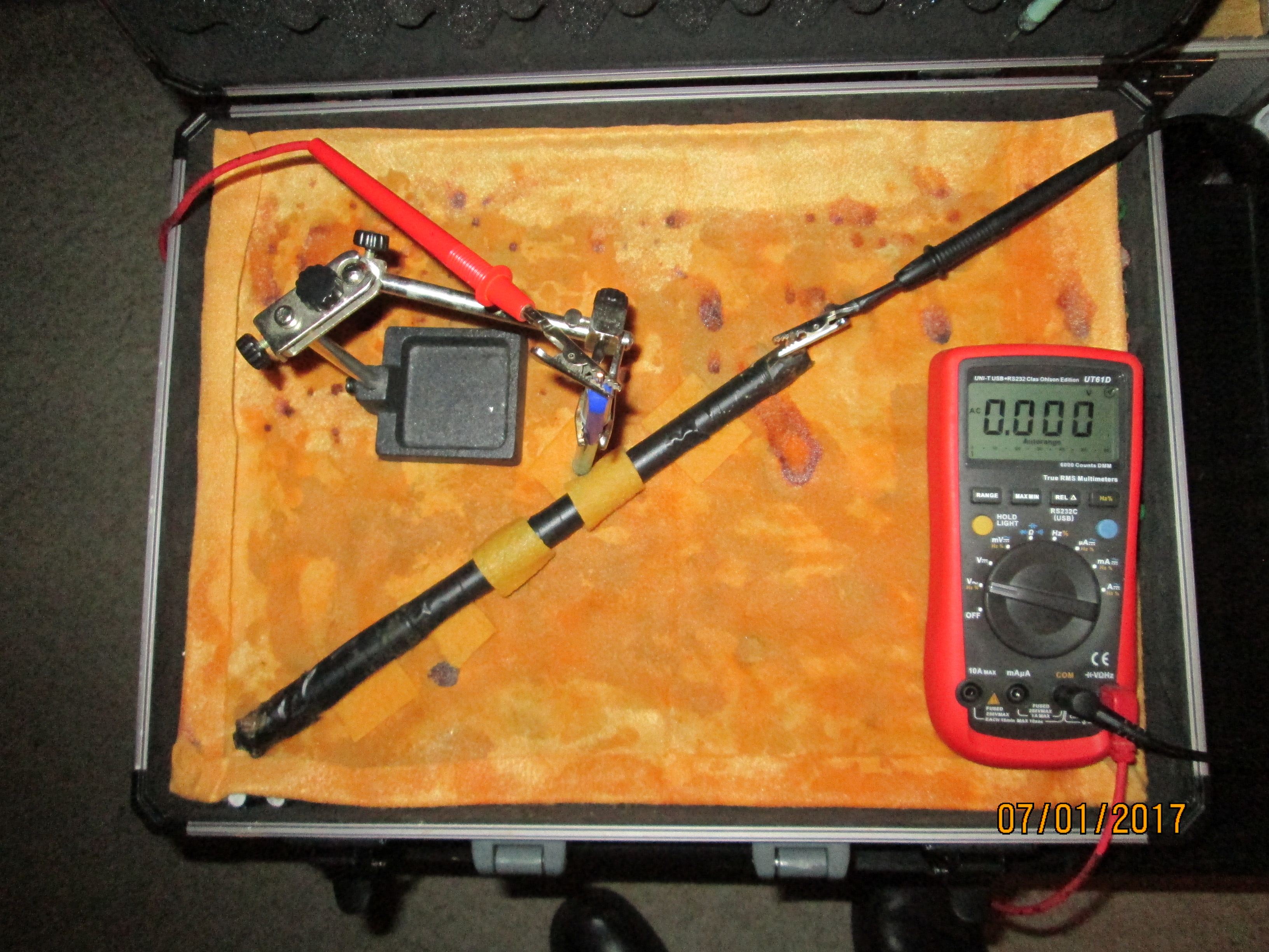
Placing the pipe-length in position results in the display returning to zero. The conductive path allows the measured cicuit to reach equilibrium.
Probing close to the pipe shows how the charges are passing through the meter to reach equilibrium. However, the high resistance in the meter blocks the current resulting in the voltage.
it can be seen that thes measurements are 'impact readings' in that the reaction potential of the stagnant copper/copper-suplhate interface equalises with the rst of the measuring circuit on impact.
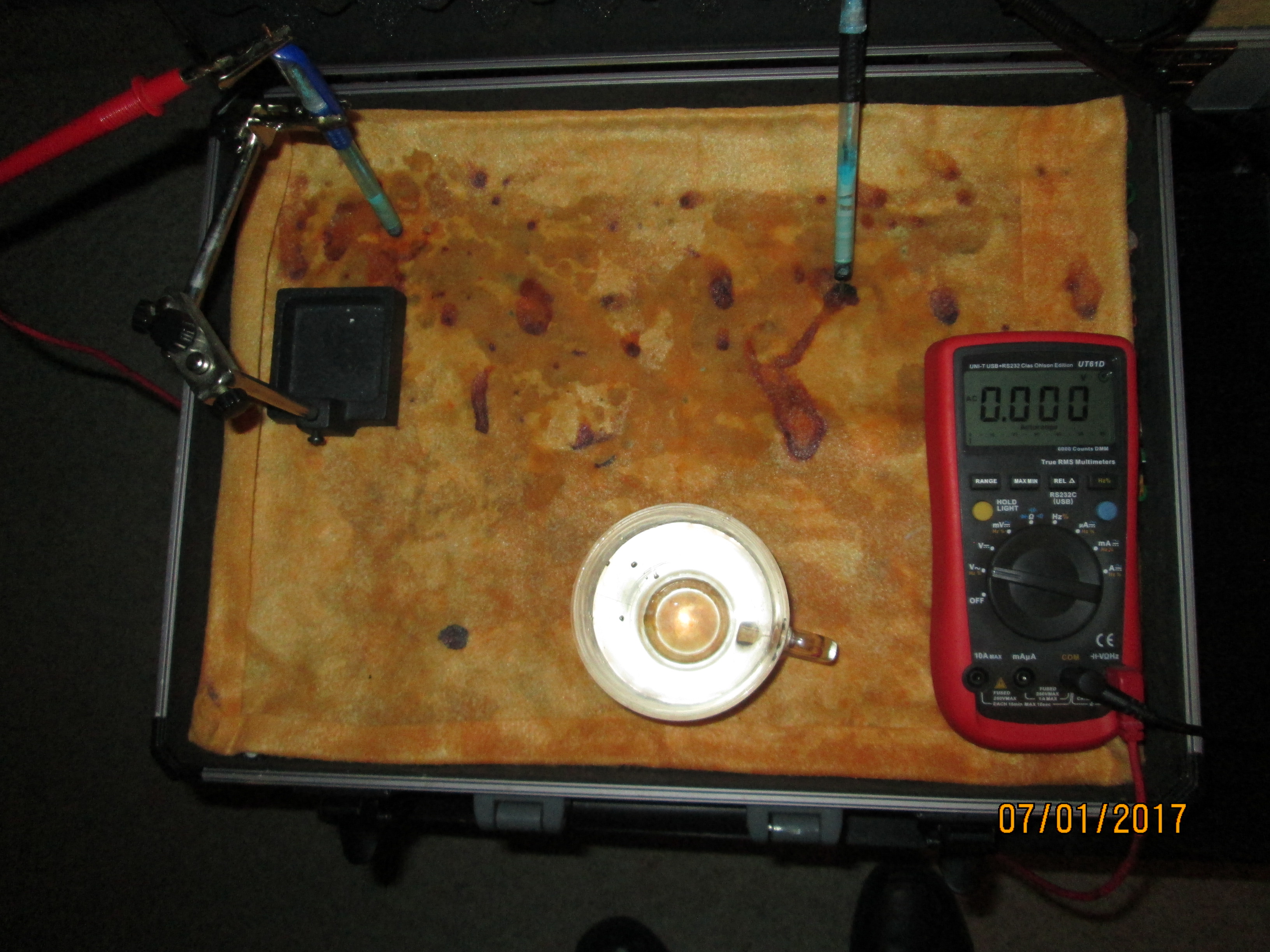
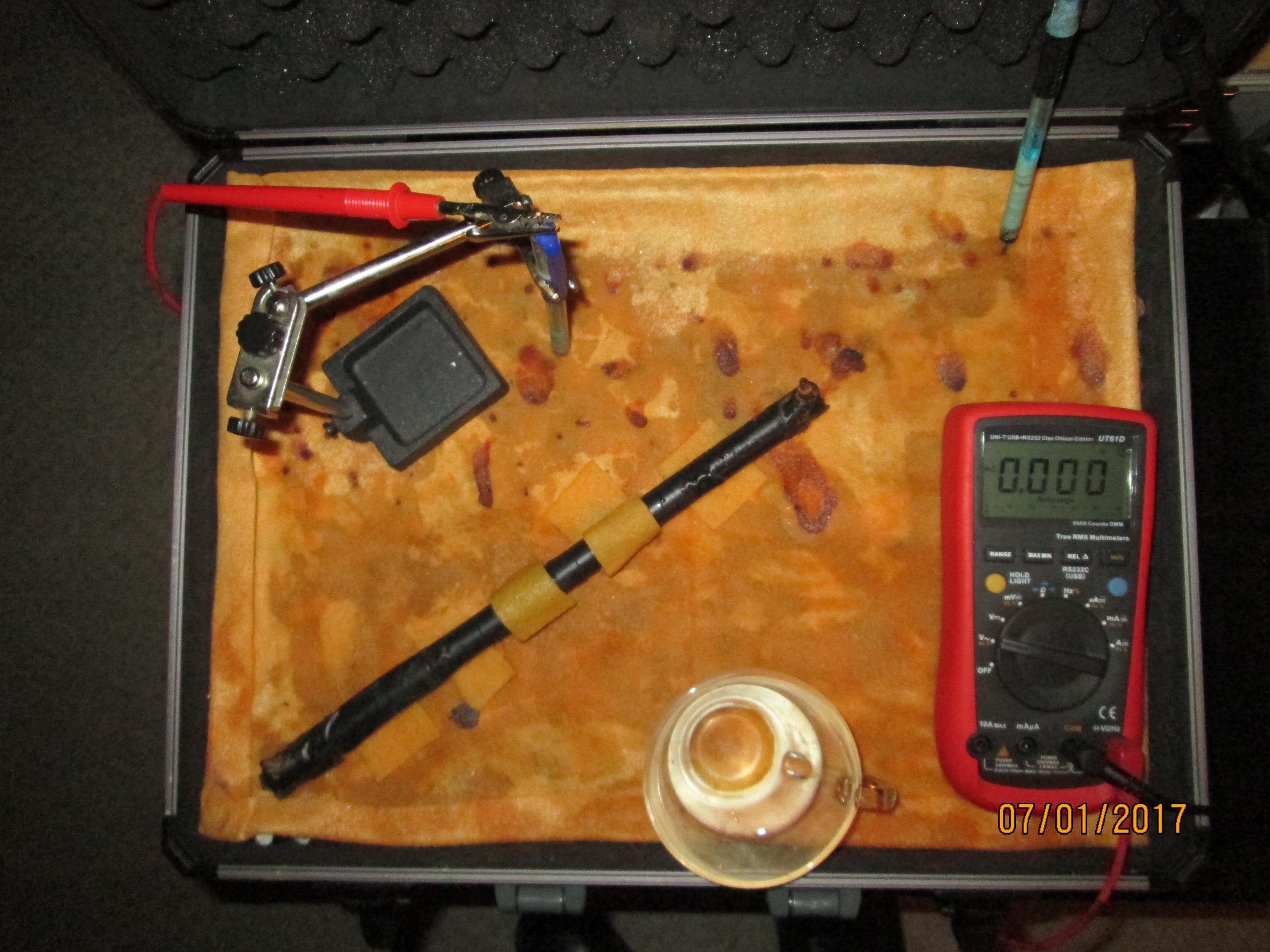
In this picture you can see a glass cup of tap water with which I started to soak the 'battery bed'.
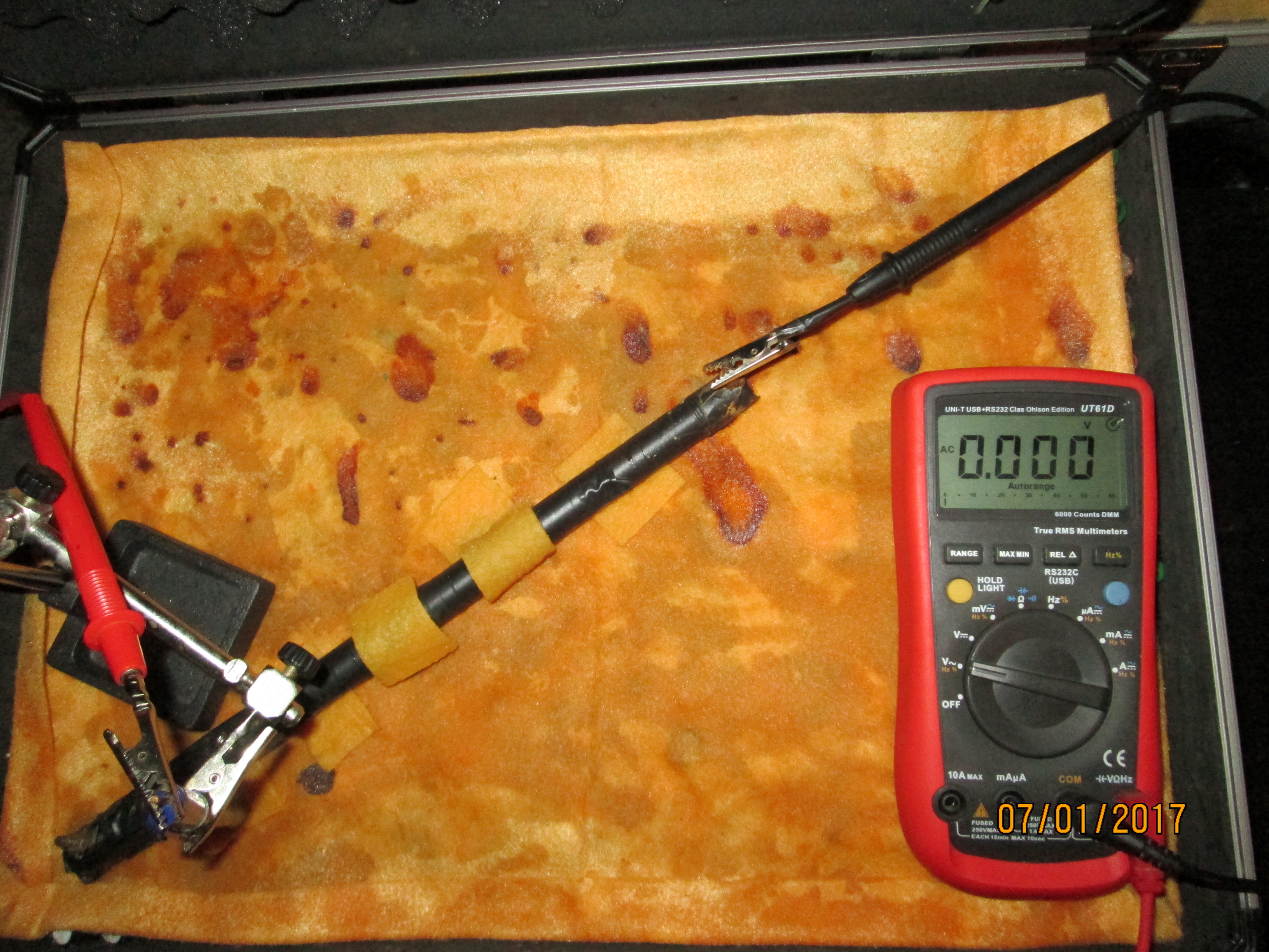
you can see that the system has reached equilibrium without current flowing and there is no voltage on the meter.
More water and a piece of cloth bridging a coating fault making continuous electrolyte with the battery bed.
The water soaks into the battery bed and allows charges to flow through the meter to equalise the measuring circuit.
The meter returns to zero when equilibrium is reached in this part of the system.
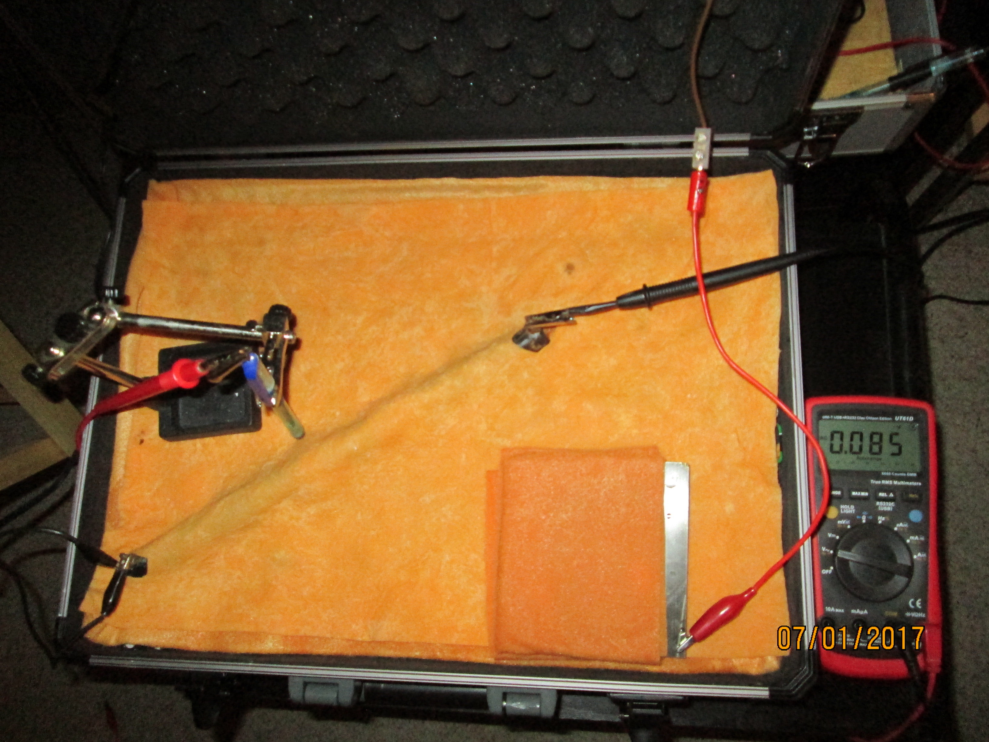
The contact electrodes are moved and we see there is again a voltage between the two.
This voltage disappears as the charges reach equilibrium through THIS particular measuring circuit.
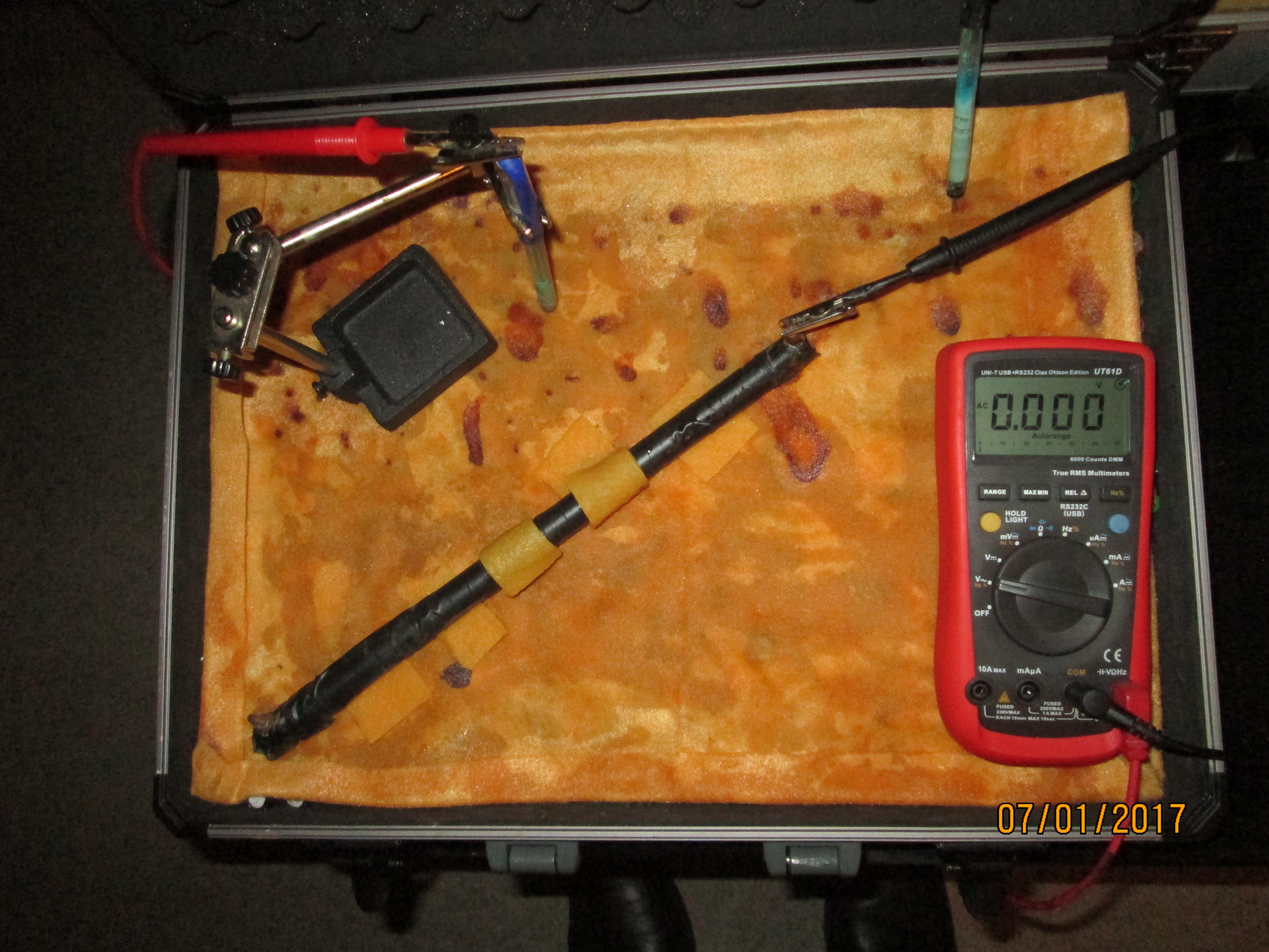
The electrodes are moved again and no voltage shows on the meter.
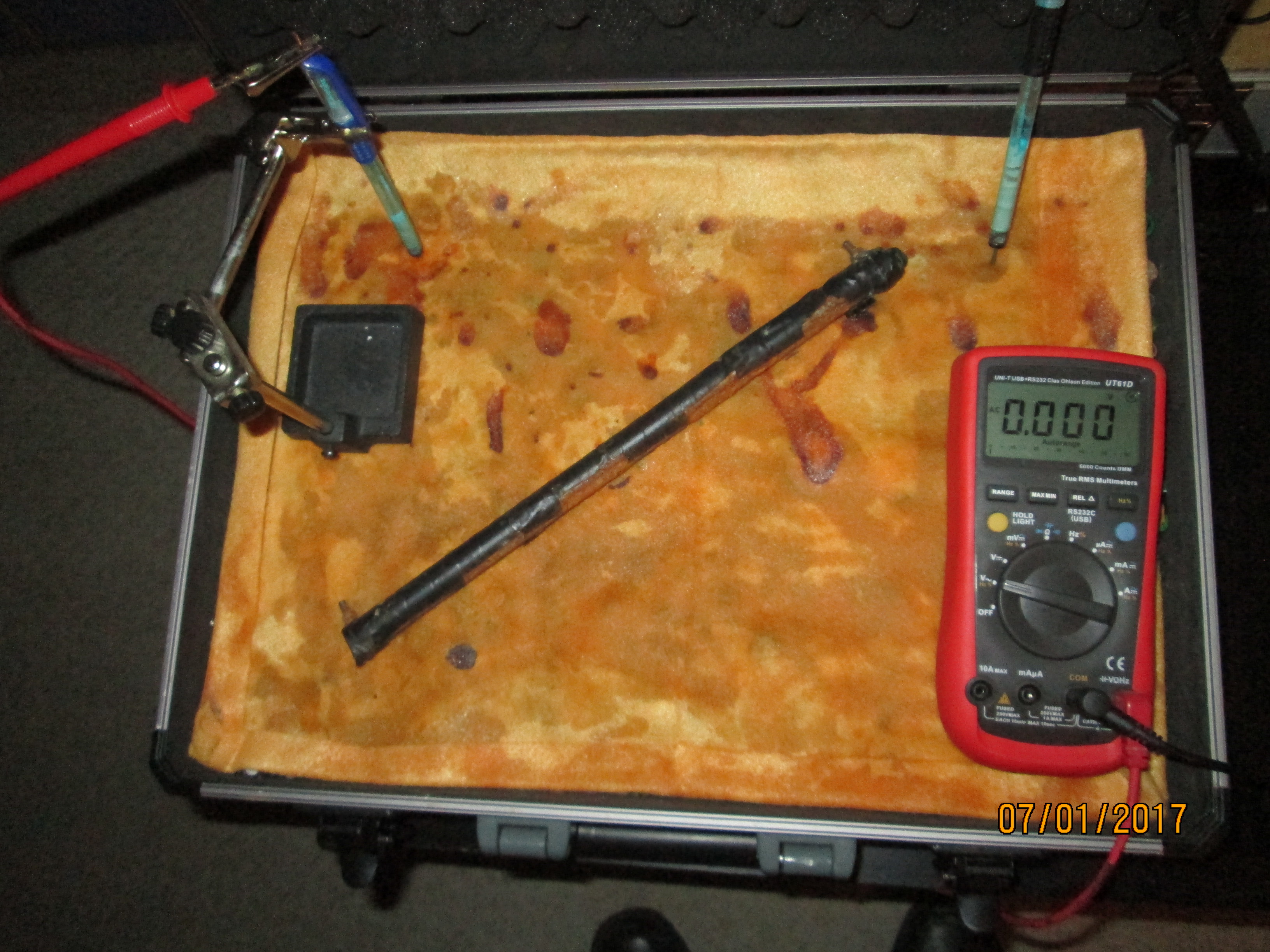
The pipe is rotated and more contact is provided to the battery bed.
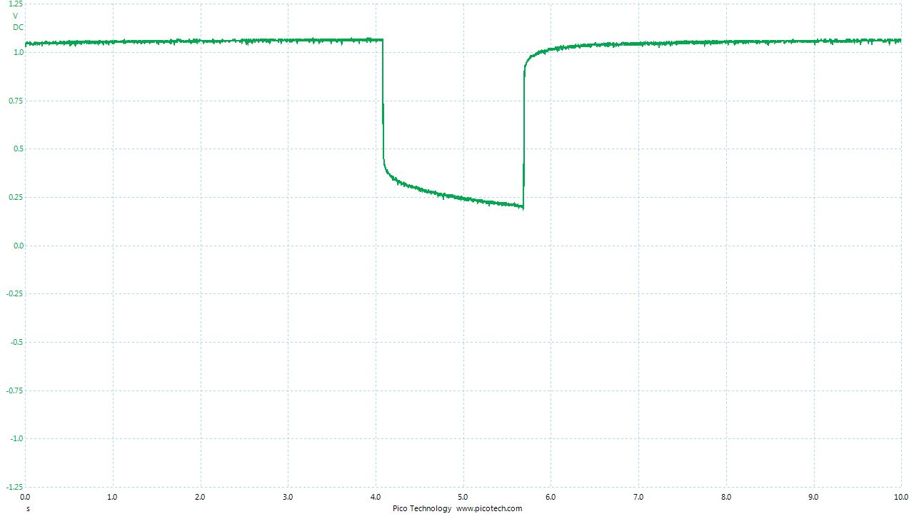
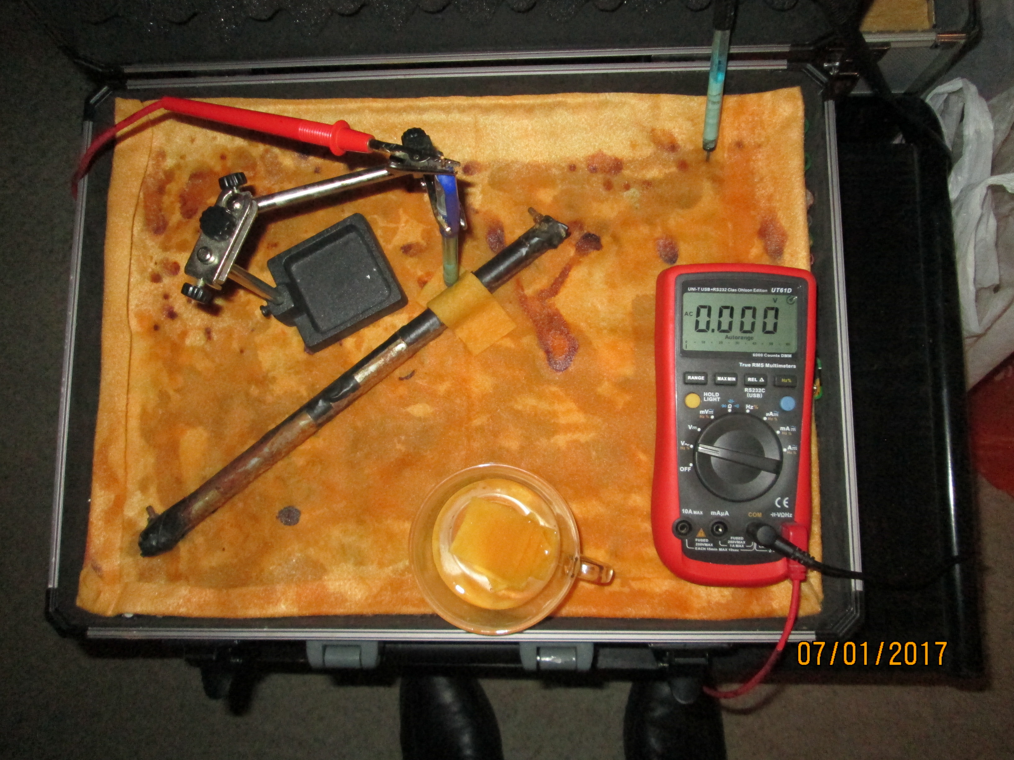
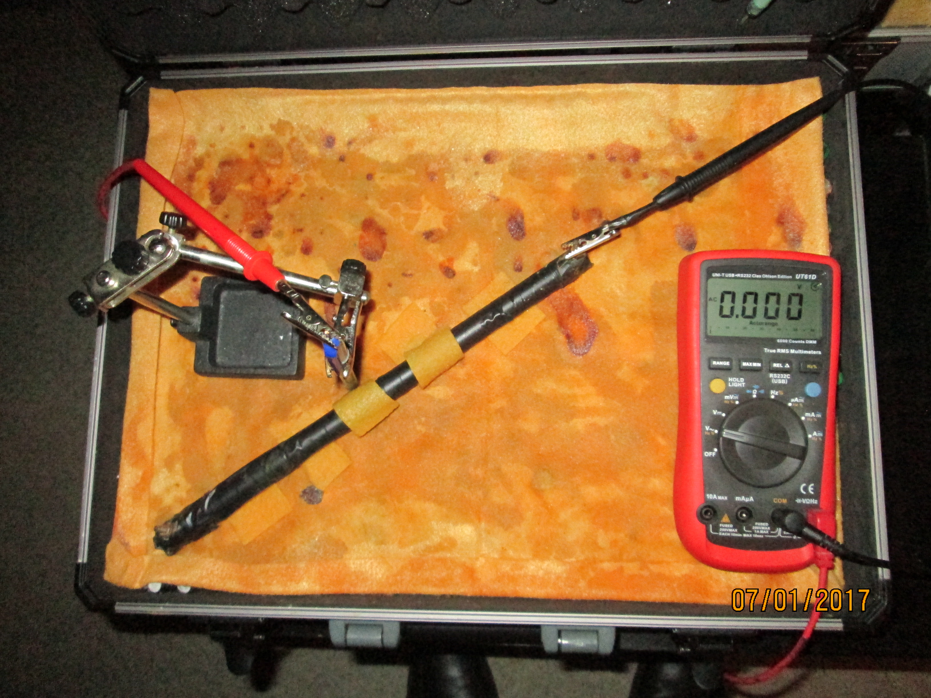
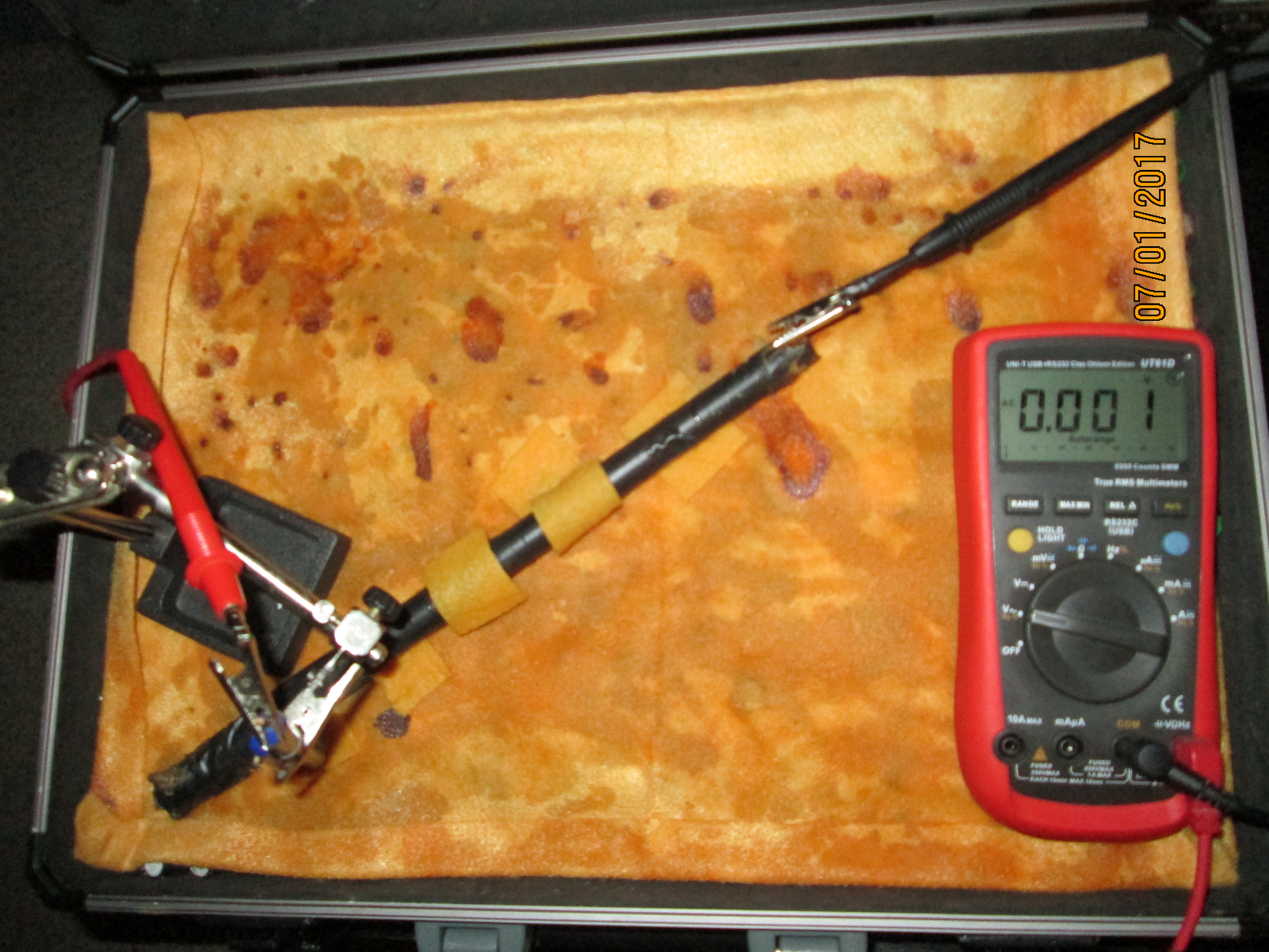
The pipe is connected to the negative terminal of the meter like a traditional 'pipe-to-soil potential measurement' and we can see that this is a voltage between two variable potentials.
There is a tiny voltage but this disappears quickly.
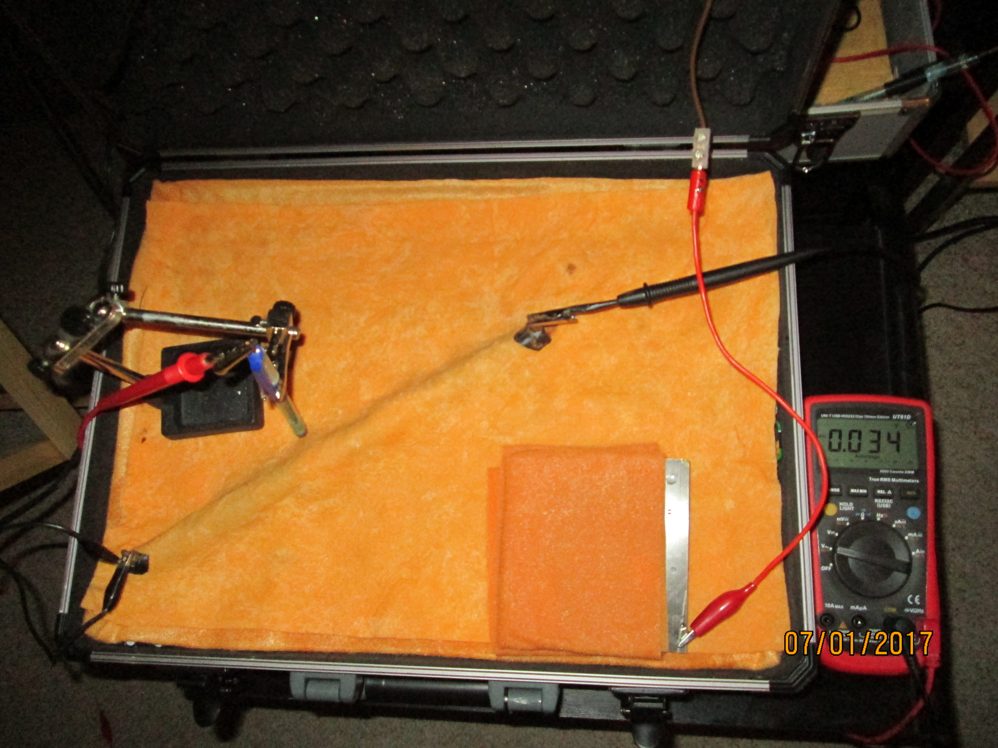
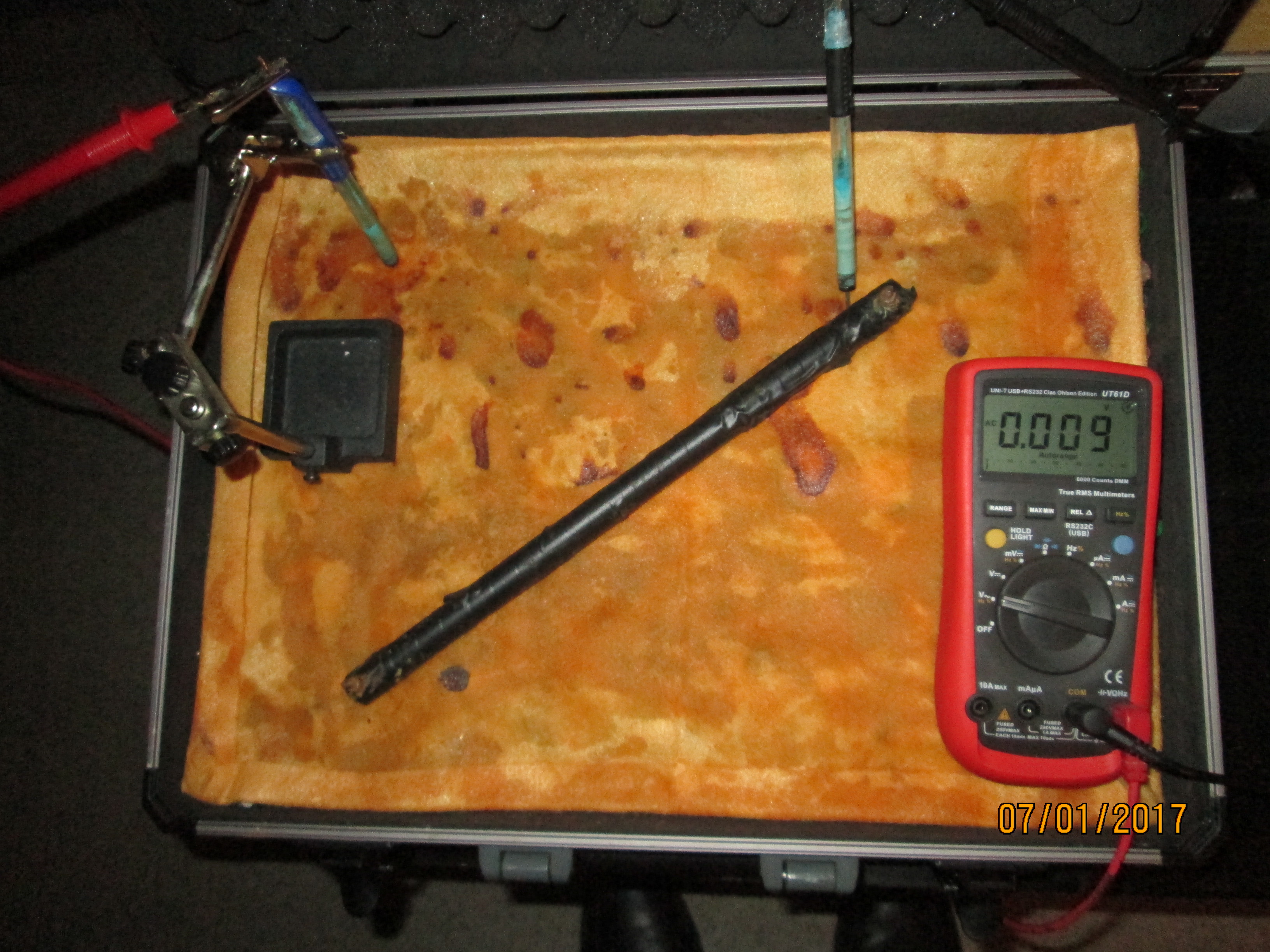
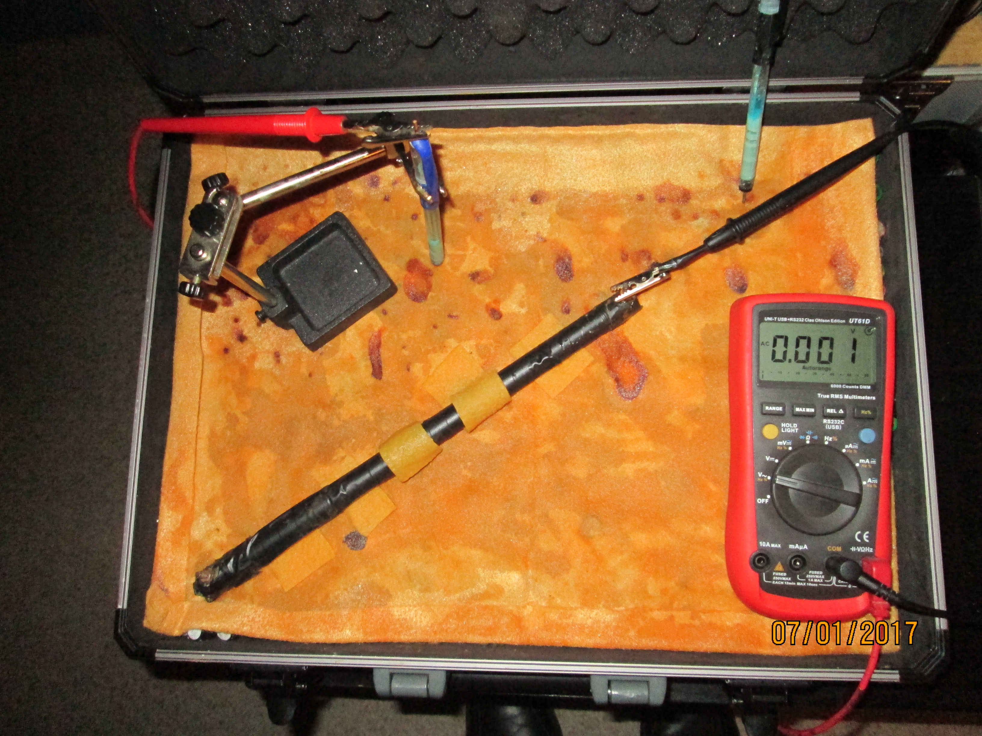
The electrode is moved to very close to the interface between the bare metal and the electrolyte and a voltage of 0.009 can be seen.
This voltage disappears with time.
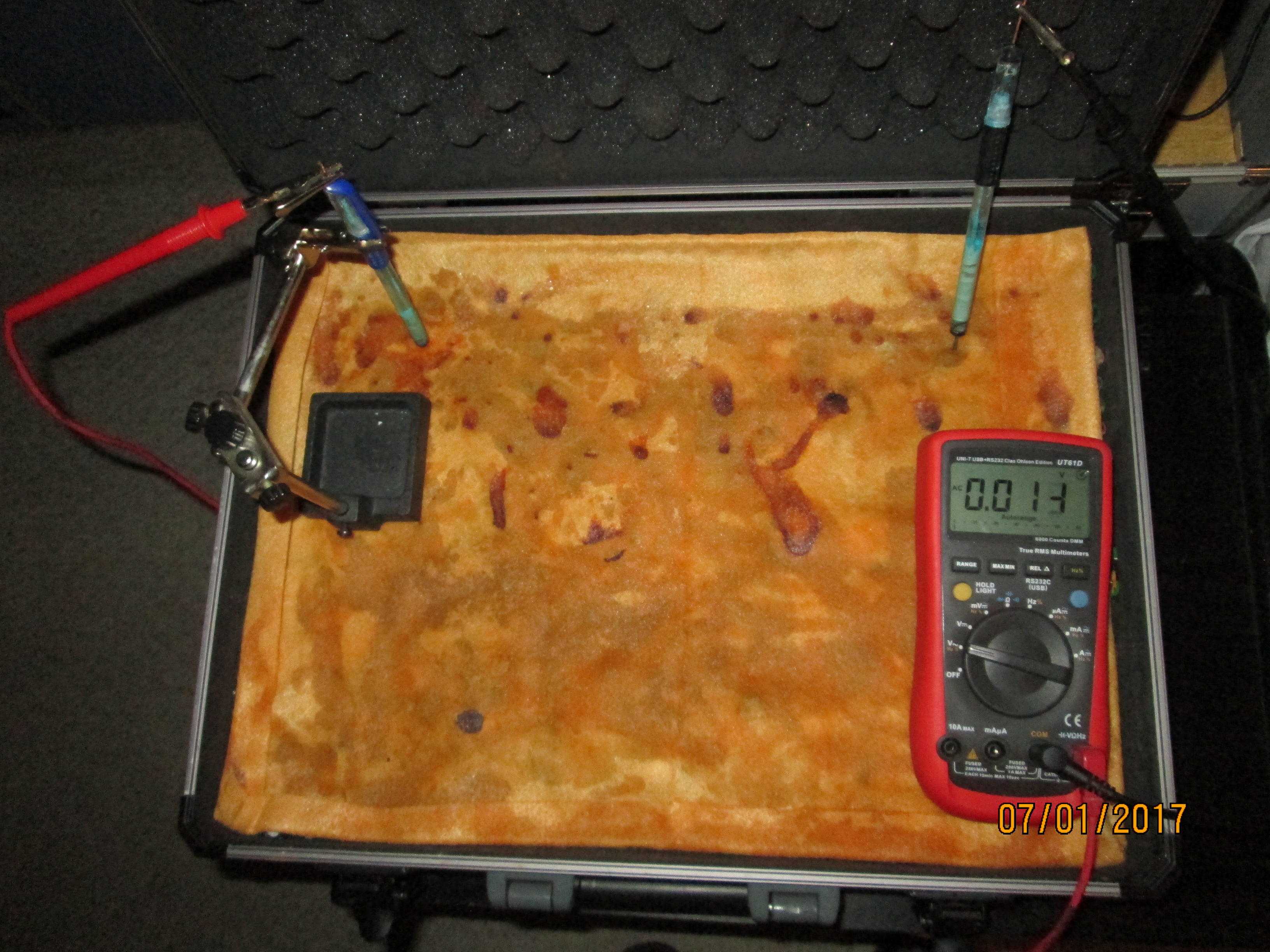
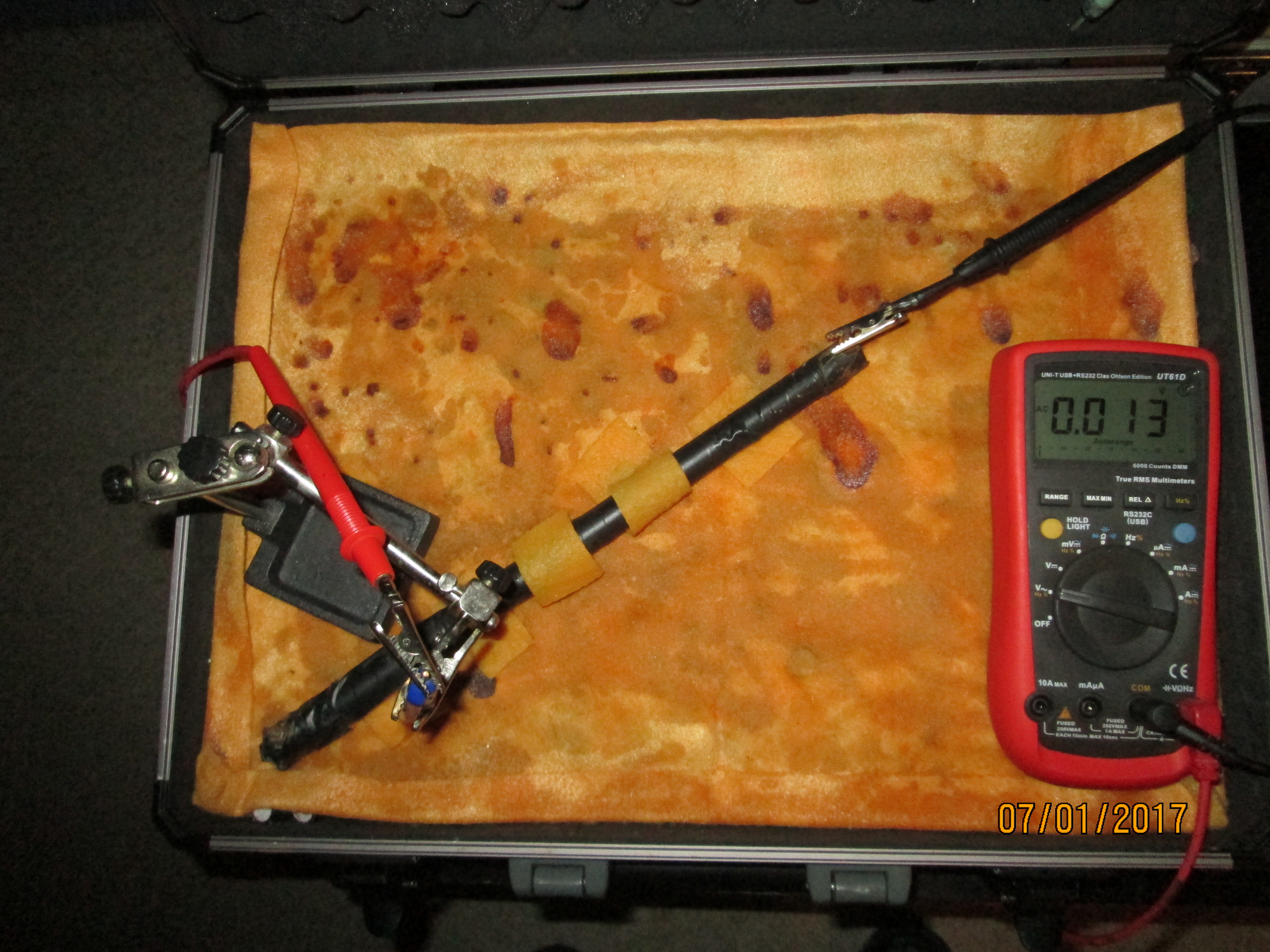
The electrode is placed in another position that shows a voltage of 0.013
This voltage also disappears within a few seconds.
The electrode is moved again and the reading is 0.004
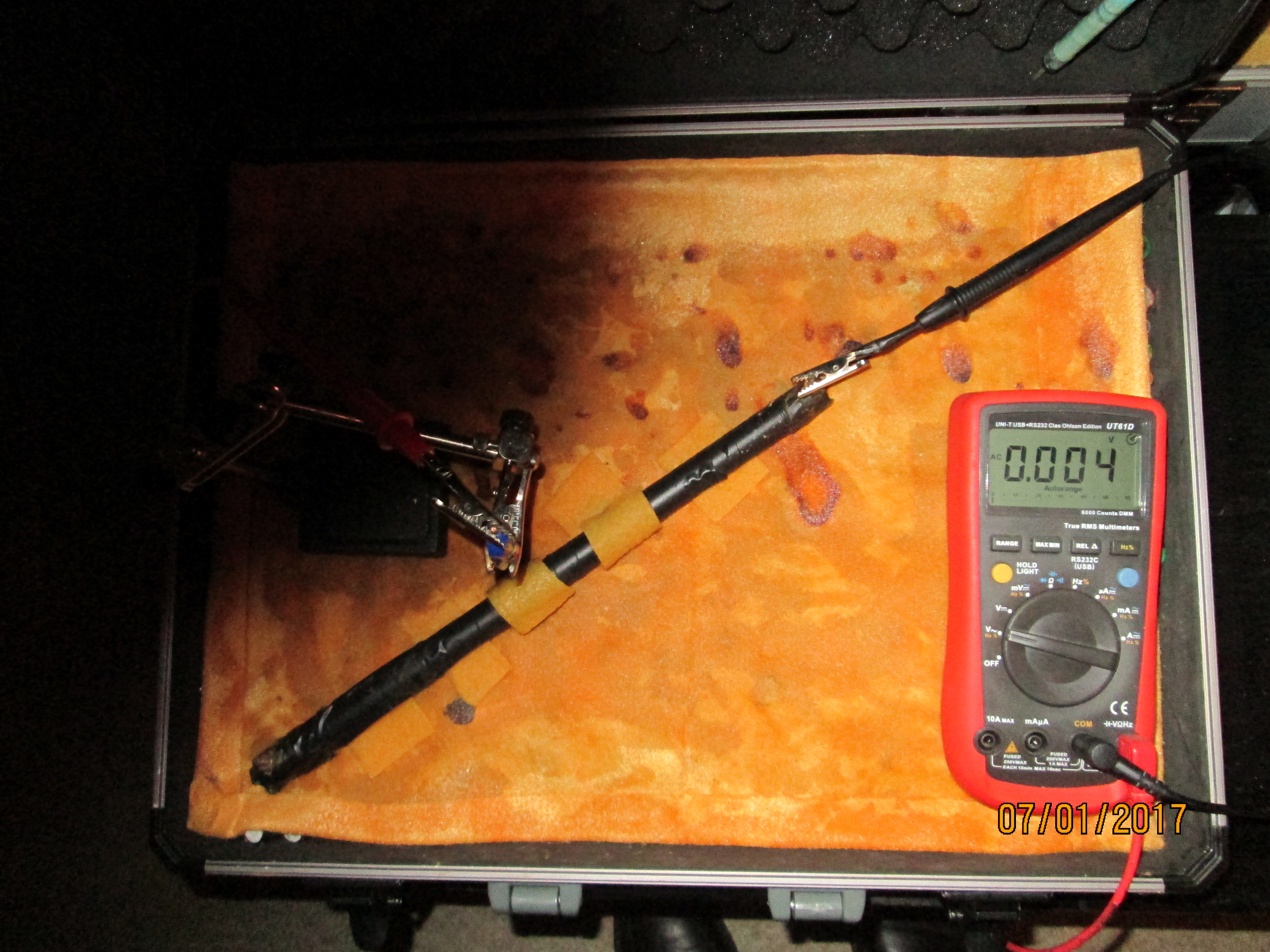
This voltage also disappears in a few seconds.
Note that the connection between the pipe and the negative (common) pole of the meter has remained unchanged.
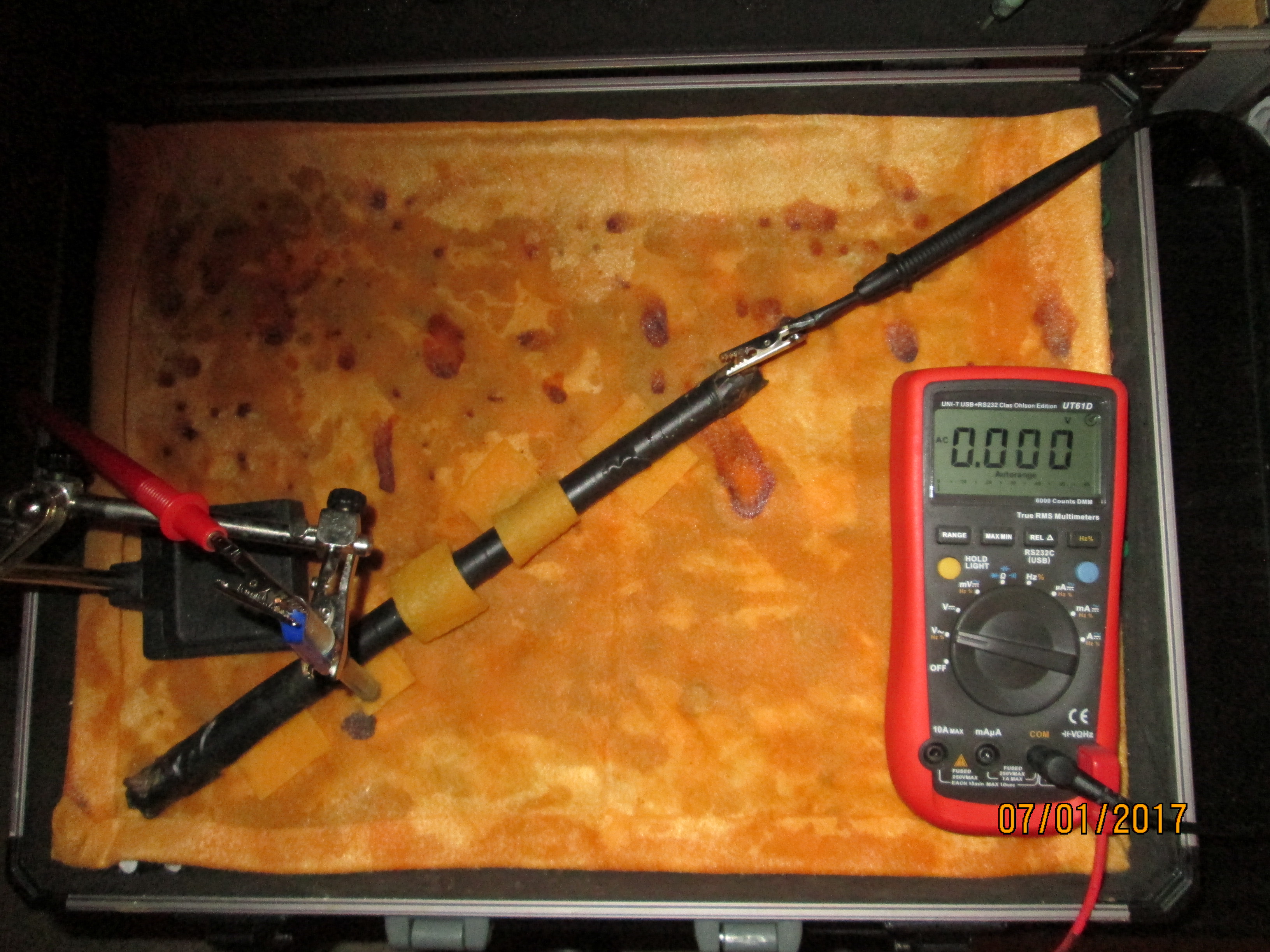
The variations in voltages displayed can only be due to the changing positions of the contact between the copper/copper-sulphate electrode and the damp cloth electrolyte.
The voltages also change when water is added to the system.
These voltages disappear as the equilibrium is reached in this new condition.
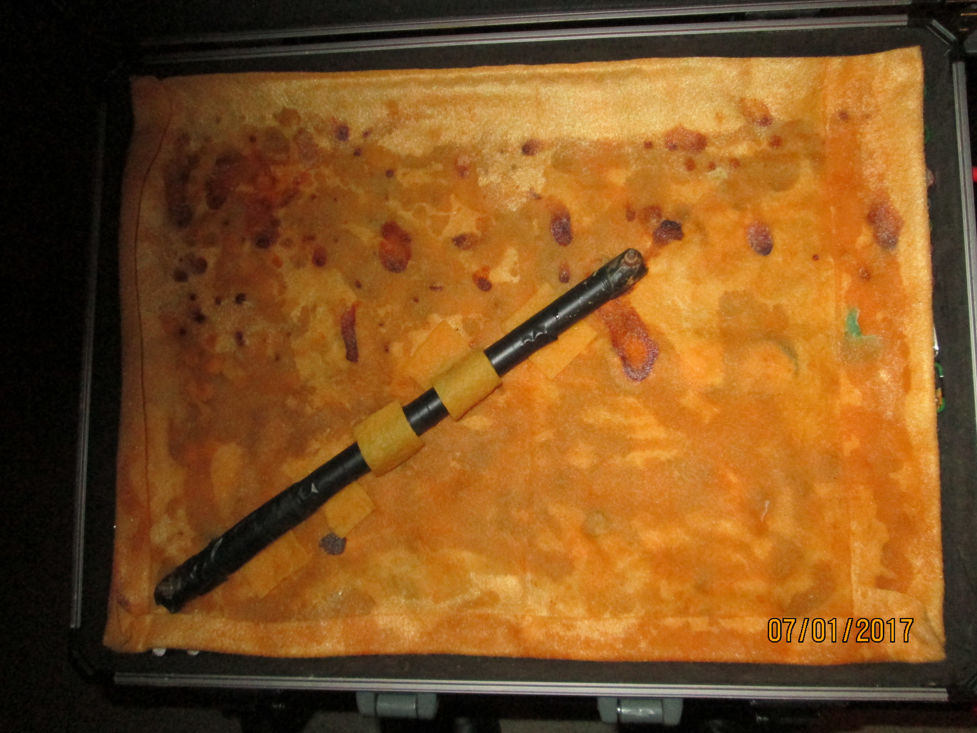
I now remove the measuring system.
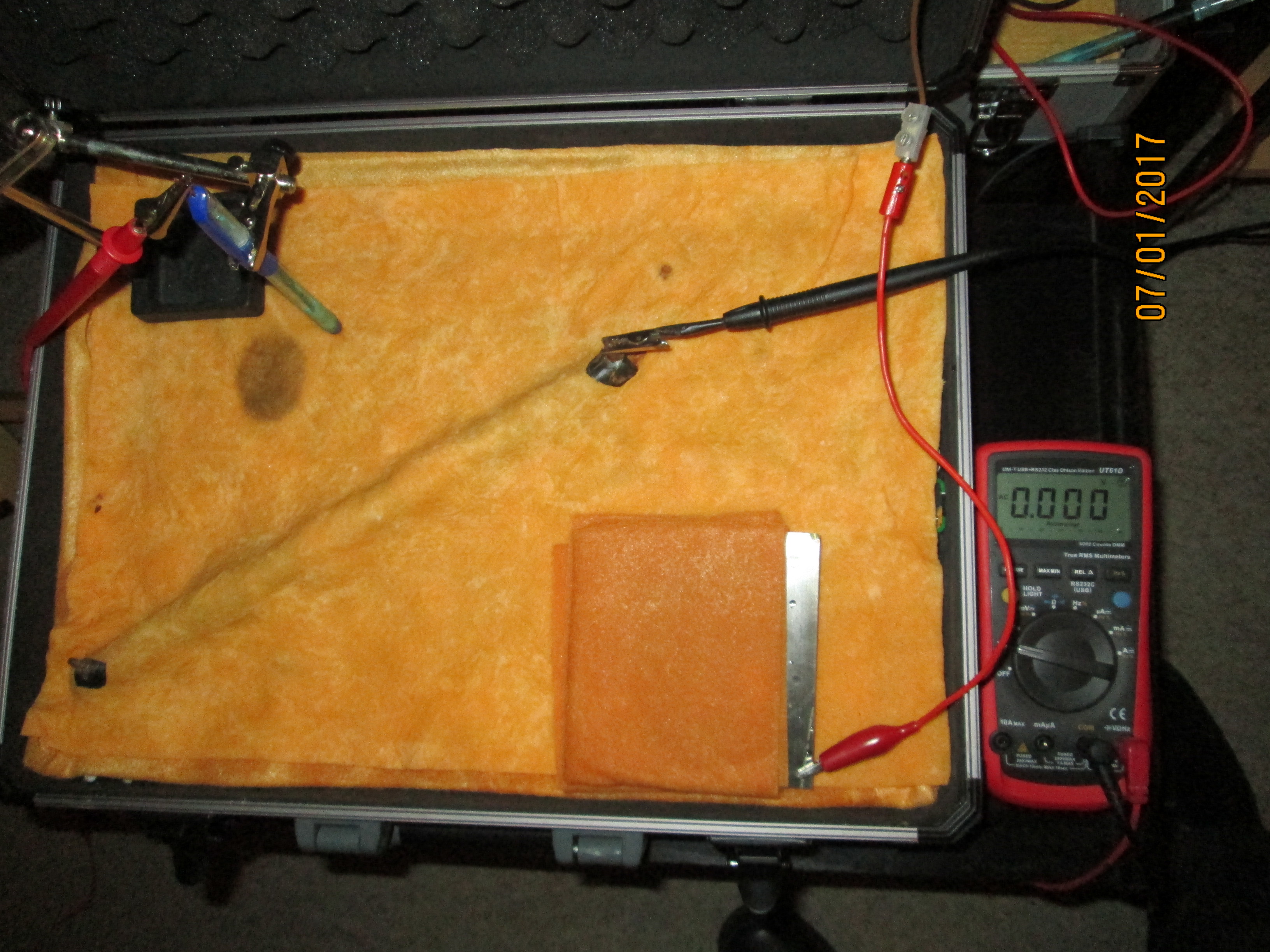
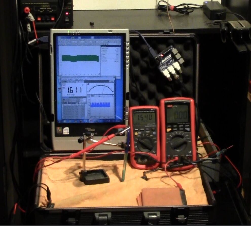
I covered the battery bed with a super absorbent cloth with holes to allow clips to be attached to the bolts through the pipe metal.
I soaked the whole thing with tap water.
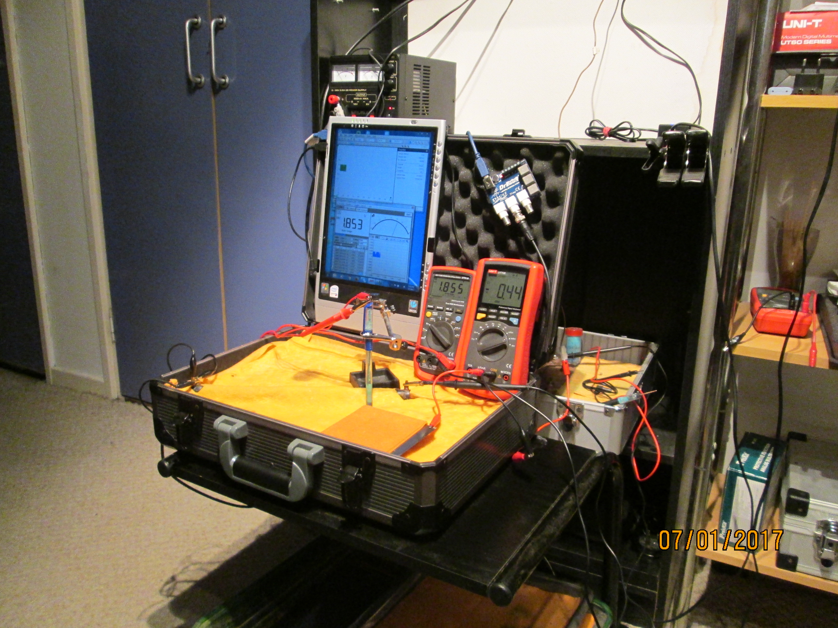
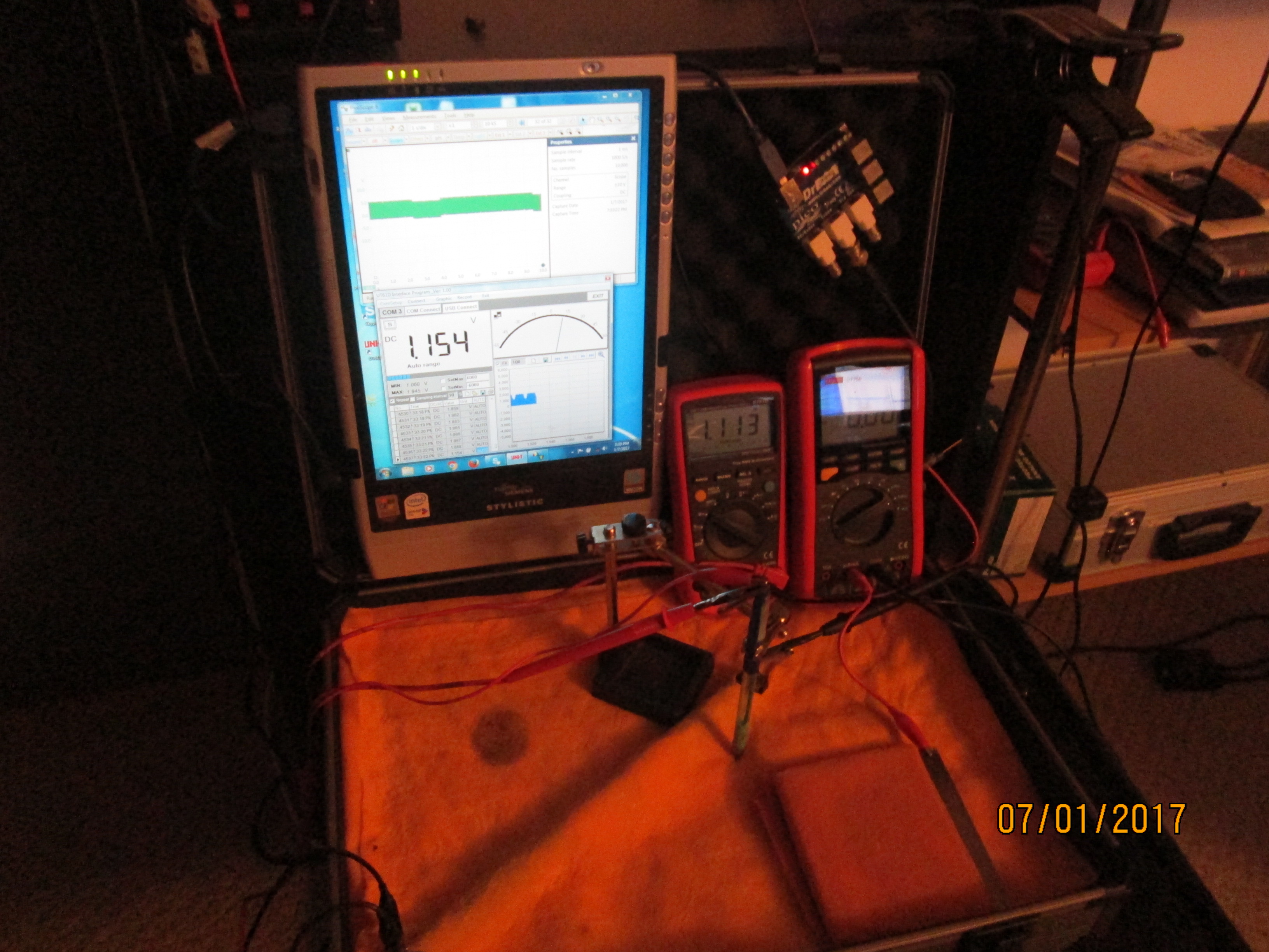
I then connected the volt meter between the pipe metal and the copper/copper-sulphate electrode as seen in the picture.
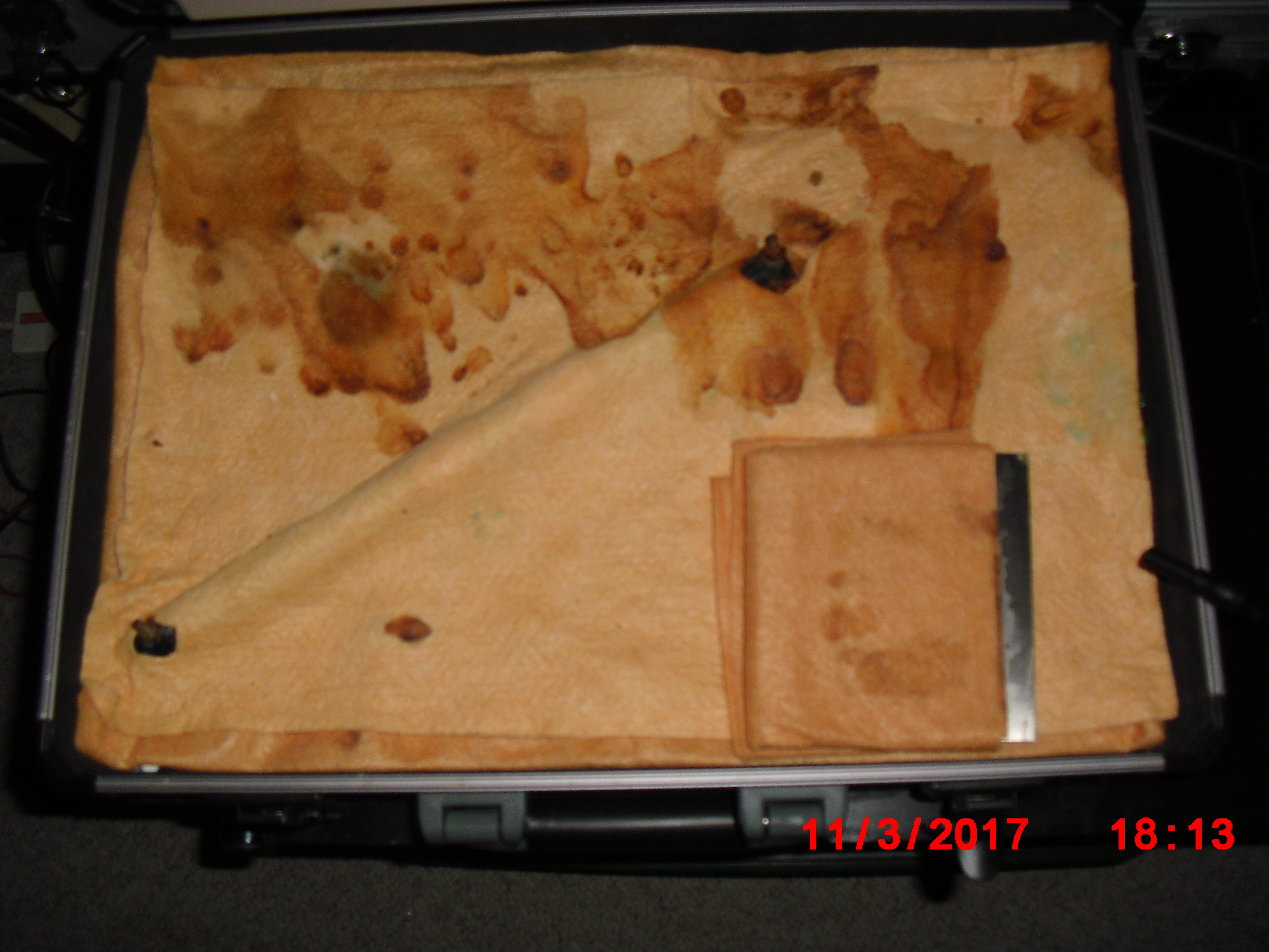
I then set up the impressed current cathodic protection system for this length of pipe by placing a steel plate wrapped in wet cloth as seen in the picture connected as the anode.
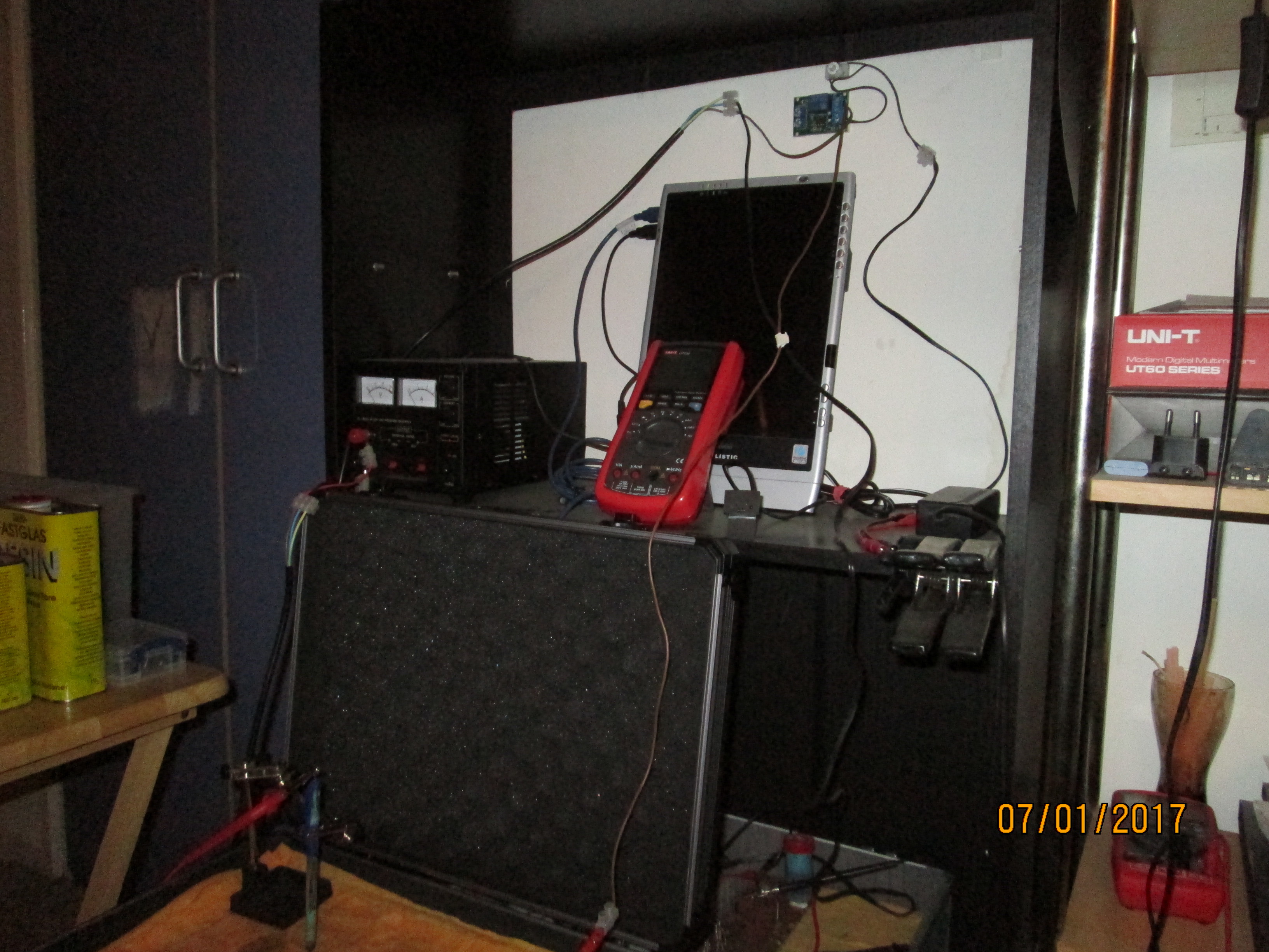
You can now see the transformer rectifier/variable power supply/battery charger on the shelf beside the tablet computer with the electronic timer abovewith the lead dropping down to the cathodic protection anode.
This picture shows the connections to the pipe and the copper/copper-sulphate electrode.
This picture shows tha connections to the multi-meter.