Three day training seminar plus two days Master Class
Period 6
Orac. The cathodic protection equivalent circuit simulator.
The first Orac evolved from the equivalen circuits that I saw drawn in 'Peabodies' and other books and papers published by NACE and the old organisations that have morphed into ICorr.
I had tried to accommodate these in what I found in my original work and job description as a CP Technician working for MAPEL in the UK on a pipeline near York.
The concept simply did not work so I made an equivalent circuit of my own to replicate what I found in the field.
I added bits and pieces using recycled parts from an old CRT TV set and a tinned square biscuit tin lid as the basis to represent the concept that I developed about remote earth.
I used this to develp theories and to try them out in parallel with data acquisition from the field.
Above ground
Below ground
Orac has been re-made
The original was stolen by someone in the cathodic protection industry.
I made another in the UK that is out on loan, and forgotten to give back
.
I made another with the help of a trainee technician in Brazil and that is still at our training centre at Guararema.
I made another in South Africa with the help of a trainee and it is still there.
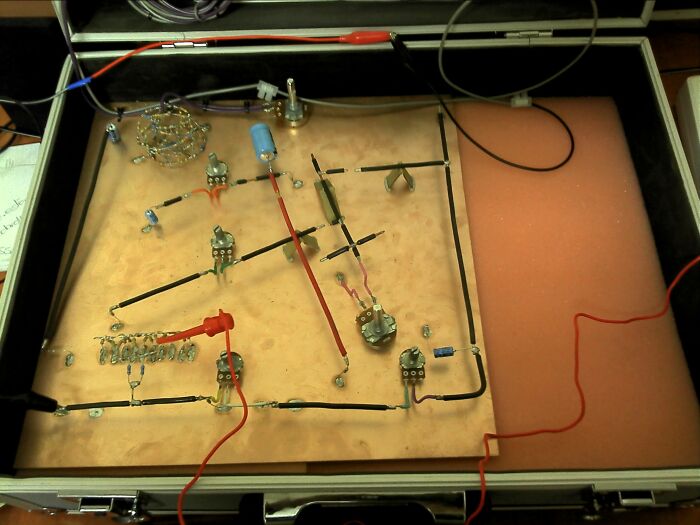
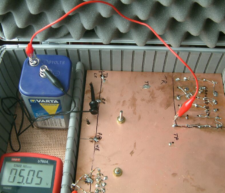
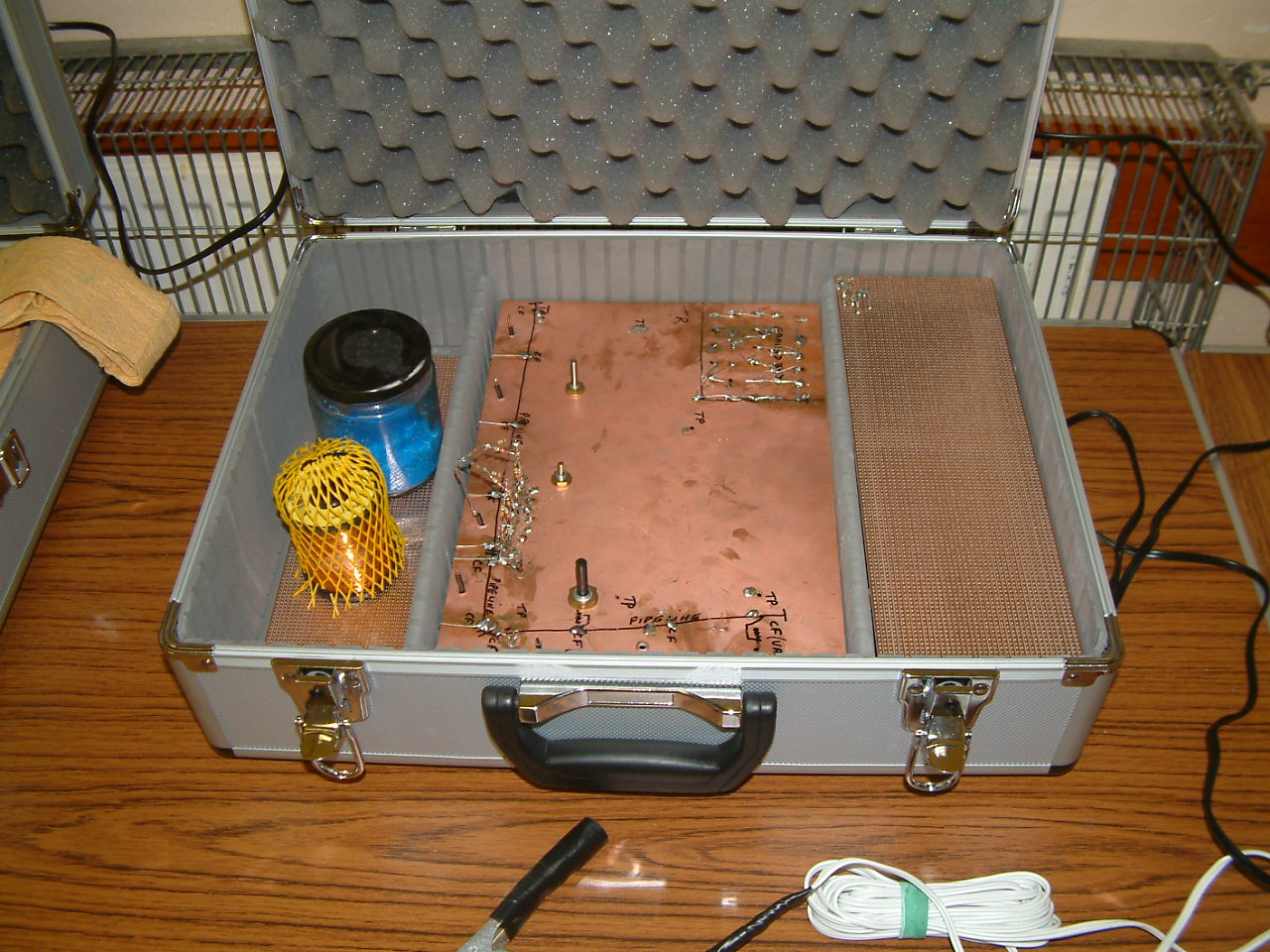
The one you see in the pictures below is part of my laboratory in the UK.
Orac works well.
( Named after the portable computer in the television series 'Blake Seven')
Orac is a demonstration of the features encountered during the measurement of voltages in cathodic protection field work.
The original Orac was based on the lid from a biscuit tin, made of a handful of scrap electronic components, a battery and two multi-meters all set in a briefcase.
It was seen by the head of corrosion control at Shell International in the Hague who wanted to buy it.
Why is Orac?
It was build to investigate the claims of some of the worlds most respected cathodic protection experts, and proves that some of their theories simply do not work in practice.
This is fine, but destructive criticism is not much good to anyone
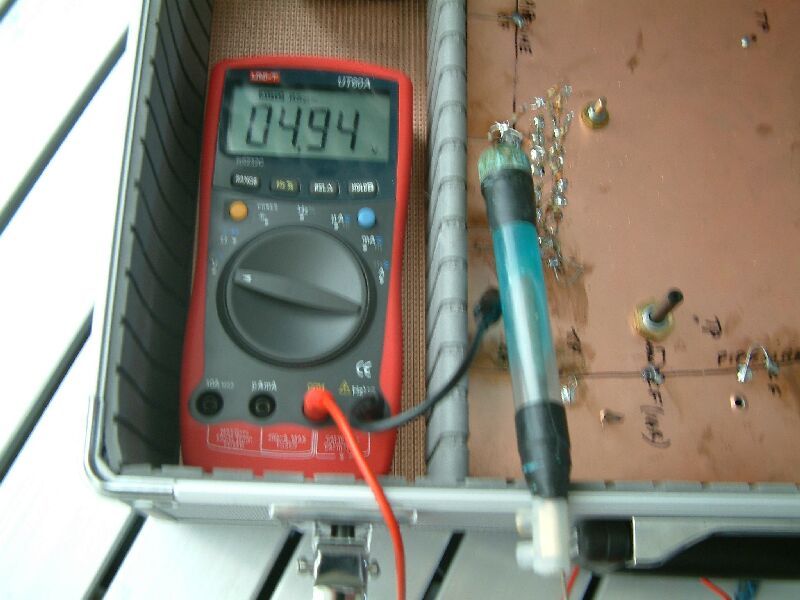
The IR drop in the soil measured at ground level
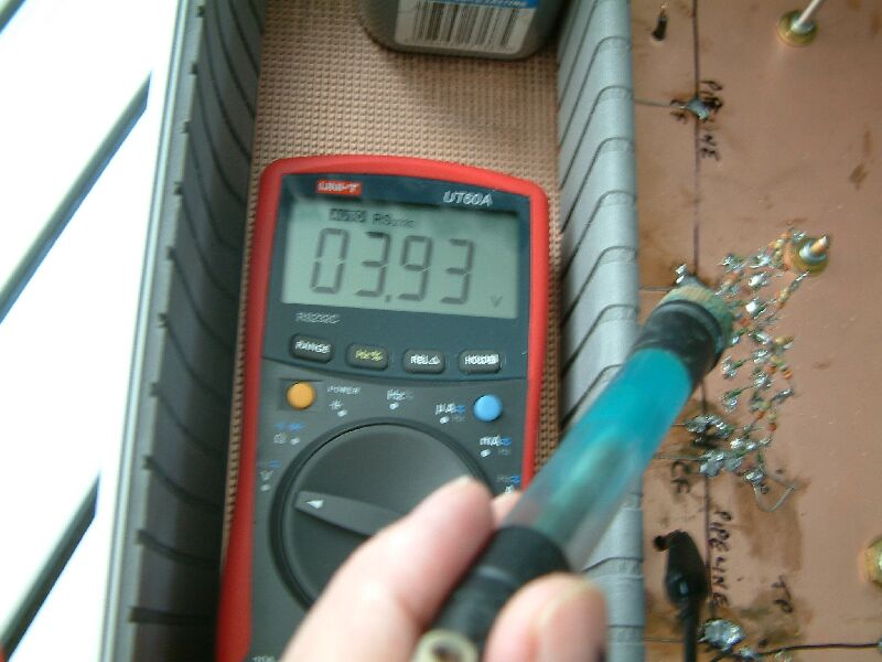
The IR drop in the soil measured 1 strata down
The IR drop in the soil measured 2 strata down
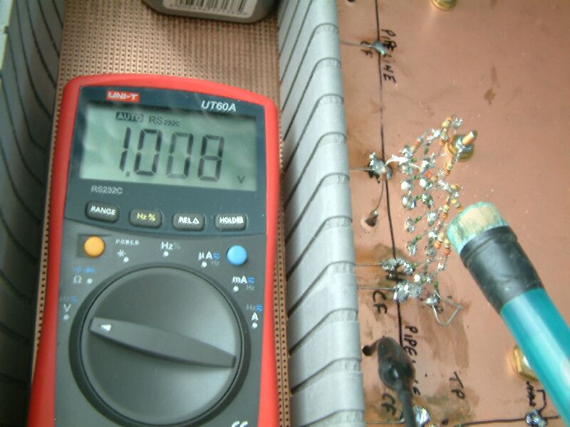
The IR drop in the soil measured close to coating fault
.
How does Orac Help?
Orac was built to show some more likely explanations for the value of voltages read during conventional cathodic protection monitoring. The electronic components have been constructed to give similar readings to those actually experienced in field work. This helps the engineer to build up a concept of cathodic protection which enables effective cathodic protection trouble shooting.
The bits and pieces
.
Meter 1
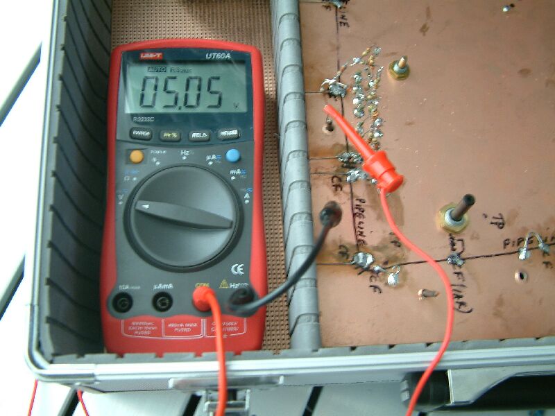
This is a typical digital multi-meter such as is used in cathodic protection monitoring. It measures similar values with similar accuracy to those used in industry, world-wide. It allows very little current to pass through the measuring circuit.
Meter 2
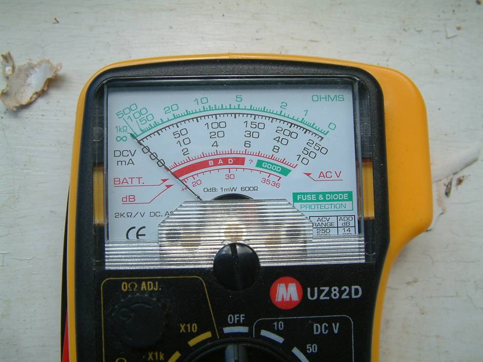
This is a cheap, analogue multi-meter based on a galvanometer. It is not particularly accurate as it requires current to pass through the measuring circuit to activate the magnet which then pulls against the hairspring, to move the indicator needle across the face of the meter.
Drawing this current reduces the potential difference between the poles of the meters, and therefore reduces the value of the voltage which is read. The reduction in voltage, caused by this meter can be measured using the digital meter and Orac.
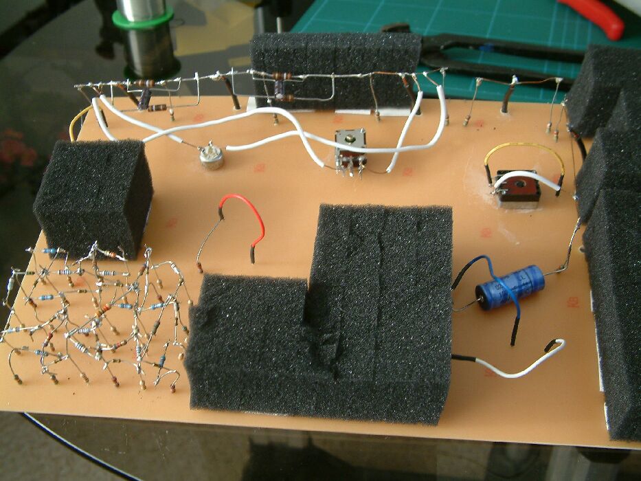
Components
The battery
This is simply a method to create an electrical imbalance in the circuit. This can be replaced with a small 'plug-in' transformer rectifier, such as is readily available to power a multitude of domestic devices.
The demonstration works equally well with either source of power and will even function when connected directly to a cathodic protection transformer rectifier in the field.
The base
This was a biscuit tin lid, made of tin plated steel sheet to which electronic components can be soldered to give a good electrical connection. This base enables a simulation of the 'mass earth' concept which is an axiom in cathodic protection theory. Both in the field and in Orac there is a virtually resistance free path for current which has entered 'mass earth'. This is now a copper sheet from any electronics supplier.
Arrangement
The input control
This is a variable resistor which allows control of the current which is fed from the battery to the base.
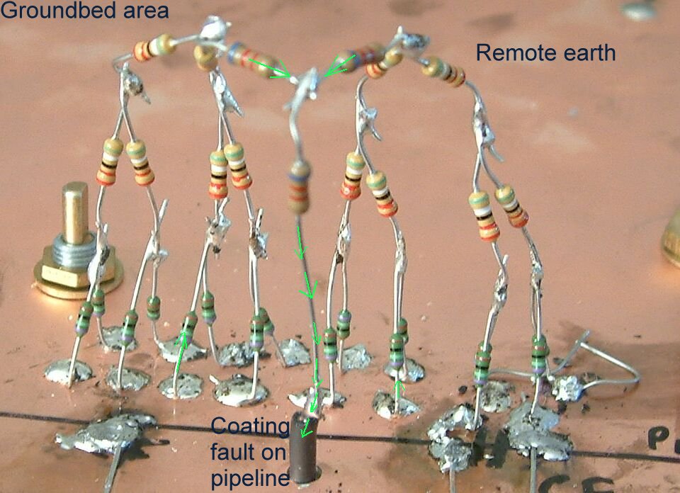
The groundbed resistors
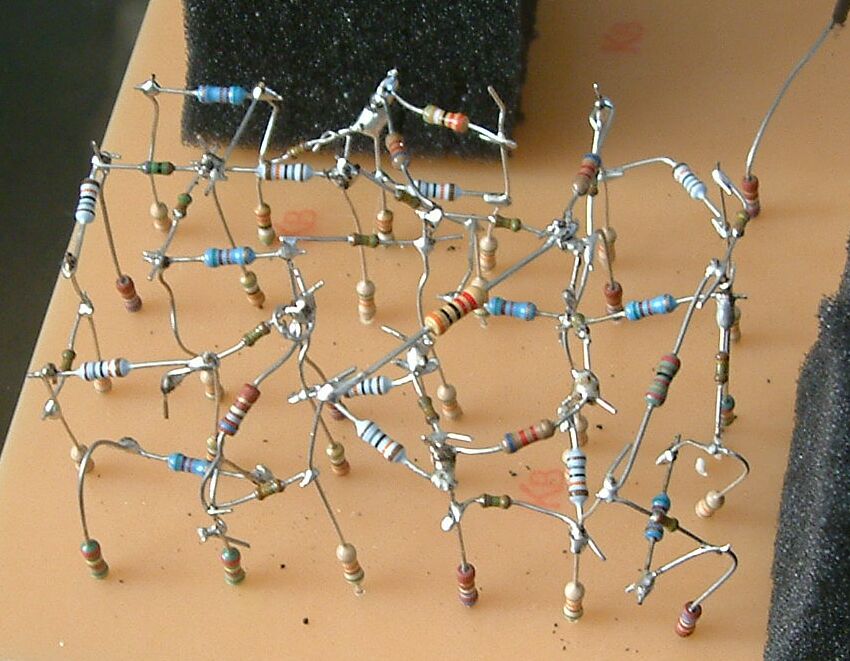
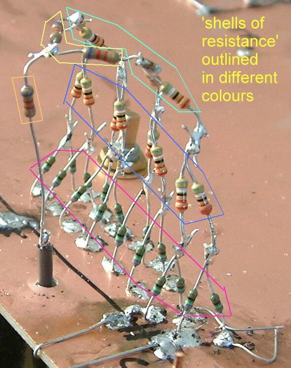
This is a network of randomly selected resistors soldered together in three dimensions. It is a concept of any part of the earth in which the current distributes itself throughout the network according to the basic laws of electricity.
This feature is provided to demonstrate the impossibility of measuring the exact amount of current passing through any particular node in the same way that it is impossible to determine the exact amount of current passing through any particular point in the earth in the groundbed area.
The whole area is 'charged up' and the current will pass to mass earth through the least line of resistance.
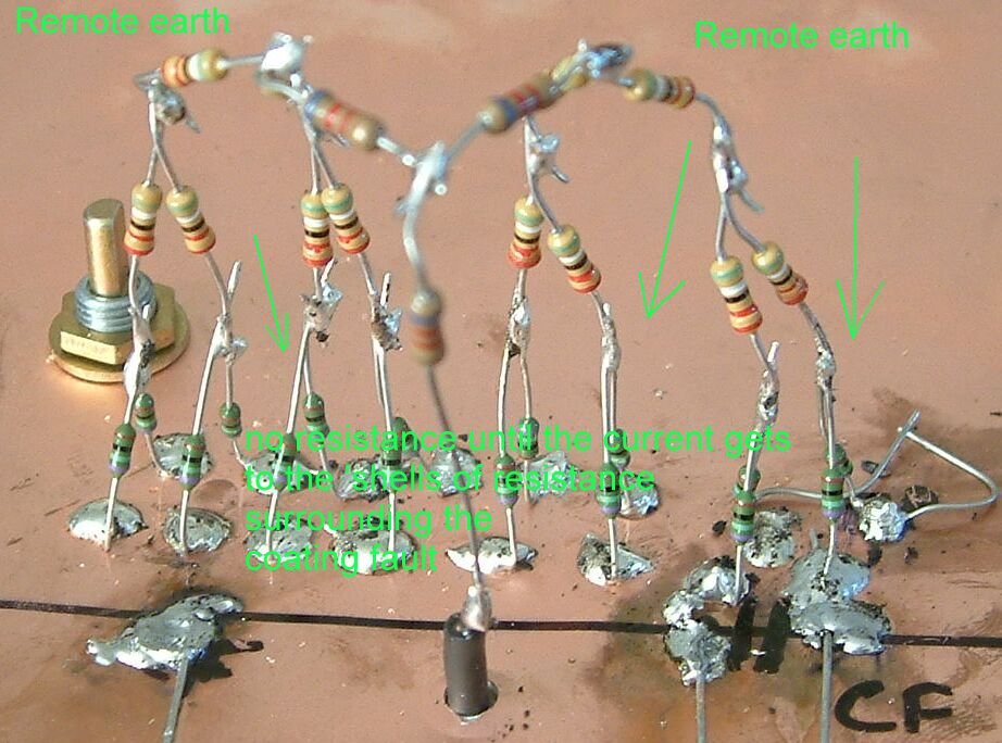
The ground itself is represented by the copper plate that has so many resistances in parallel that there is no resistance.
Where there is a boundary of resistance (the pipeline coating or the wire insulation) and a less resistant path through, shells of potentials will be formed that can be measured on the orac model as they can in real life.
Groundbed to remote earth resistances
Two variable resistors connect the groundbed network to the base. This enables the demonstration of the effects of a high groundbed resistance, and illustrates the advantages of seeking to build a low resistance groundbed.
The pipelines are conductors and are represented on Orac by insulated wires with resistors (in series) to represent distances of pipelines. Variable resistors make it possible for the pipelines to be of any length.
The pipelines
The pipelines are represented by a series of resistors soldered end to end to show the typical resistance in the metal of a fairly long, large diameter, pipeline.
The actual value of the resistance of each pipeline depends of the wall thickness, the diameter and the length but the values in Orac will be found to be fairly typical, and can be calculated from the colour coding of the resistors which are used. It was necessary to use some resistor in parallel during the construction of Orac, but these can be imagined as pipeline manifolds for the purposes of experiments.
The coating resistance
The pipeline is connected to the base on 'pillars' which are in fact high resistances and two variable resistances. Each of the fixed resistances can be perceived as the actual coating resistance and the variable resistors can represent coating faults.
It is possible to adjust the total resistance of the coating and the disposition of this resistance along the pipeline to simulate areas of poor coating . in the original Orac the variable resistors were under the plastic cover and difficult to access in the same way the it is necessary to excavate to the pipeline to make any effect on the coating.
It is appreciated that the pipeline can be short-circuited to other buried metal but this can be simulated on Orac by direct connection between the 'pipeline' and a suitable variable resistor connected to the base. This was one use of the extensions on the right hand side of the original Orac but I have now several other experimental models that can be linked to represent complex cathodic protection systems balancing many pipelines and facilities.
Test posts
The test post positions
These are represented by access holes through which the meter connections can be made. This is the same as making a direct connection to the pipeline metal through a test facility in field work, and the same affect is achieved on Orac.
Earth contact positions
These are provided as bare ends of the wires that poke through the plastic cover of Orac. These are displayed in this way so that the connection can be made using the meter probes or by making contact with the porous plug of a standard copper/copper sulphate electrode.
Model extensions
A red and a green wire are provided at the right hand side of Orac to enable the pipeline and the groundbed to be connected to other demonstration pieces.
Electrolytic capacitor
This is included to demonstrate the including it in the circuit can reproduce the effect of the so-called decay in cathodic protection which is manifest when the cathodic protection is switched off. Orac can therefore demonstrate 'immediate off' readings using a recording voltmeter or data-logger.
What can Orac demonstrate?
Orac was built to test the truth of statements made in leading text books relating to cathodic protection practice. Many of these quote 'equivalent circuits' and have illustrations similar to those that are seen in electronic drawings. It is therefore logical to build the arrangement and apply the potentials to become familiar with the behaviour of the meter when used for monitoring the electrical behaviour. Theory has to be correct for the model to work, but when it does it then makes the theory easy to understand. Orac enables all experiments to become readily repeatable and facts to be properly established.
Orac can demonstrate the difference between an analogue meter and a digital meter.
The meter is placed between the two potentials and the current passing through the meter allows the potentials to equalise, to a limited extent.
The analogue meter continues to demand energy to balance the elastic memory of the hair spring, whereas the digital meter can be likened to filling up a number of containers in a row and displaying the amount of the fill on a screen powered from an independent source of energy.
One of the demonstrations
Orac can demonstrate the difference between analogue and digital meters by the following procedure.
Connect the battery terminals to the two clips.
Connect the digital meter to test post 1 and a half cell position in normal soil.
Switch on the meter and adjust the output until the meter reads 1.5 volts.
Set the analogue meter to the 10 volts DC range.
Connect the negative pole of the meter to the green extension lead from the pipeline.
Watch the digital meter reading, while touching the positive analogue connection to the same half cell position connection as that connected to the digital meter.
Note that the reading reduces from about 1.5 volts to about 0.72 volts.
Watch the dial of the analogue meter while touching its positive connection to the same half cell position on Orac as that connected to the digital meter.
Note that the meter needle shows about 0.5 volts.
Connect the analogue meter permanently across the same connections and disconnect the digital meter positive connecting.
Note that there is little detectable movement to the analogue meter caused by the disconnection of the digital meter. Touching the digital meter lead to and from the connecting points will confirm this.
Important basic understanding.
This experiment proves that the meter simply short circuits the two subject potentials and that the higher the resistance in the meter the lower the ratio of error that it introduces.
Applying this principal to cathodic protection monitoring it becomes apparent that the introduction of digital meters increased the apparent success of applying cathodic protection, by increasing the value of the voltages that were measured.
Cathodic protection engineers were able to attain the criterion of -0.850 volts and pipelines were considered to be protected, but some time later failed due to external corrosion.
The position of the electrode is critical.
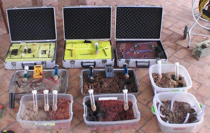
Orac can allow engineers to measure voltages and current measurements that can be computer analysed. These can be compared directly to measurements made in the field during CIPS surveys
How to do this using Orac.
By leaving the negative terminal of the digital meter connected to the pipeline at test post 1 and moving the positive connection to a variety of connecting points, it can be seen that the resistances between the groundbed and the electrode have a major effect on the readings.
Four connections are provided and labelled 'half-cell positions in normal soils'. These connections are extensions of a network of resistors which are connected to the base. This is the same concept as connecting the electrode to a random point on earth while taking a conventional 'pipe to soil potential reading' during cathodic protection monitoring. The connection is at the earth surface to a finite point of resistance as represented on Orac.
Connect the DC V pole of the digital meter to the pipeline through test post 1 and the common pole of the digital meter to the left hand wire of the 'half cell positions in normal soils'.
Equivalent CIPS survey
Switch on the meter and connect the battery.
Adjust the output to get a steady reading of 1 volt.
Move the positive meter connection to the second position from the left, then to the third and then the fourth.
Note that this produces little change, in spite of the slightly different resistances in the measuring circuit.
Move the positive meter connection to the wire labelled 'dry tarmac'.
Note that the meter reading reduces from 1 volt to about 0.95 volts. This is due to the increased resistance between the base and the connection point. It reduces the amount of current which is available to be measured by the meter and thereby reduces the reading.
Move the positive meter connection to the wire labelled 'dry concrete' and the reading reduces to about 0.666 volts for the same reason that it reduced as described above. Note that the resistances in steps 5 and six are introduced in the measuring circuit.
CIPS continued
More the positive connection of the digital meter to the position labelled 'half-cell positions at the top of the excavation'.
Note that the reading is about 1 volt and that the arrangement of resistors is similar to that of the 'normal soil' positions. This section has been constructed to show the reasons for the lower readings obtained when moving the electrode closer to a coating fault immediately before it has been exposed by excavation. Of course, once the fault is uncovered it has no connection to the electrolyte and the pipeline is effectively 'coated by the air.
Move the positive connection of the digital meter progressively down the row of wires labelled 'moving half-cell down excavation', noting each reading. Note that the readings reduce as the resistance between the electrode and the pipeline reduces. This can be regarded as a different effect from that of a resistance in the measuring circuit. Here we are looking at the true voltage measurement and not an error due to the inefficiency of the meter.
The potentials at each pole of the meter are of closer value due to the passage of current through the cathodic protection system. This is the improperly named 'IR drop in the soil'.
CIPS continued
In the field this voltage is due to the resistance of the soil where the cathodic protection current passes onto the metal. Where there is no coating fault, this voltage is high, as demonstrated on Orac at the 'top of the excavation', which is out of the area of influence of the low resistance path to the pipeline. As the contact point moves closer to the lower value of resistance between itself and the pipeline the voltage between this point and the pipeline is reduced, as seen on the meter.
Typical readings on Orac during this procedure are as follows:-
Top of excavation -1.034 volts
Position 2 -1.034 volts
Position 3 -1.059 volts
Position 4 -1.048 volts
Position 5 -0.453 volts
Position 6 -0.342 volts
Position 7 -0.159 volts
Position 8 -0.007 volts
Similar values will be obtained when moving a 'half-cell' electrode down the sides of an hole which is being excavated towards a coating fault. Indeed this is a method of guiding an excavation to the coating fault following a condition monitoring survey.
Contact with the pipeline.
Moving the contact point along the pipeline has undetectable effect on the reading.
During the massive voltage survey conducted by North Thames Gas, during the 1980's I was part of a team of technicians working for the Slough Office in the High Wycombe area. We were measuring voltages between the pipeline and an electrode which was stepped along the ground above the route of a coated, steel, high pressure gas pipeline. This was done at 10 meter steps while the impressed current cathodic protection was automatically switched on and off at the closest transformer rectifier.
In order to carry out this survey we had to use a long thin wire (actually armature winding wire) as a connection to the pipeline through the normal cathodic protection test post facilities. These test posts were positioned at access points such as road crossings, and were up to 1 mile apart. We would connect the wire to the test post and unreel it from a spool which we carried, the other end of the wire being connected to the positive pole of the high resistance digital voltmeter.
On one occasion I was instructed to chose two test posts approximately 1 mile apart and to take two voltage readings at each end. The thin wire was to be connected to the local test post and then to the test post one mile away.
The readings showed that connecting to the pipeline one mile distant made no detectable difference to the voltage shown on the meter from that shown on the meter when connected locally. However, the reading was altered considerably by moving the location of the electrode a few meters. We carried out several tests to prove these facts and submitted a report, but got no feed back or further information.
This feature can be demonstrated on Orac by the following procedure.
Connect the battery and adjust the output to achieve a voltage of 1.500v when the negative terminal of the meter is connected to test post position 1 and the positive connected to 'half-cell in normal earth'.
Connect the negative terminal of the meter to the pipeline at test post position and note that the voltage has not changed.
Connect the negative terminal of the meter to test post 3 position and note that the voltage has not changed.
Calculate the total resistance along the 'pipeline' on Orac and you will find that it is the equivalent to the total resistance in the metal along several miles of large diameter steel pipeline.
Movement of the position of the negative connection produces little or no change in the voltage but movement of the positive connection produces significant variations. This is the most significant fact in understanding monitoring of cathodic protection and the measurement of voltages in the study of the corrosion reaction.
Using Orac can give an engineer a good concept of the electrical balances involved in the application of cathodic protection in the field.
Orac 1984