Three day training seminar
Period 2
This period will bring the understanding of cathodic protection into the everyday life.
This is necessary because scientists have failed to pass their knowledge to the end users of the science that are the engineers, technicians and field operatives who are applyning the science of corrosion control in the field every day.
This next pictures is a very small part of the scientific reasoning behind the codification of electrochemistry.

This is a picture of the laboratory arrangement that is necessary to add real values to the characters used in the equations.
This closed circuit laboratory technique has two potentials that can be compared and measured as a voltage.
1. The reaction potential between the reference metal and the electrolyte in which it is submerged and
2. The reaction potential between the electrolyte and the 'working electrode' that is being studied.
This can be set up to measure the values in multiple corrosion cells as found in ALL field work
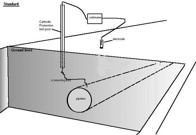
In cathodic protection field work the negative pole of the meter is attached to the metal of the pipeline and the other is attached to the copper/copper-sulphate electrode that we are told to regard as a reference potential.
However this belief failed and ways were sought to correct the errors in the theory.
The theory of this 'pipe-to-soil potential measurement'
The idea is that we know the potential of the reaction between copper and copper-sulphate and can compare it with the reaction of the pipeline metal to the ground at that location. This is comparing two reactions and is NOT measuring a half-cell reaction as they do in a laboratory.
It is quickly apparent that the measuring circuit has more than two potentials in series because the readings change when the electrode is moved.
This is the method that has been used for over 50 years to obtain field data to examine the status of corrosion on pipelines and facilities globally.
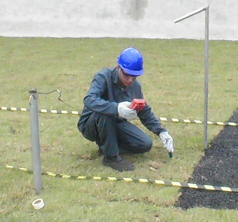
The only change in the measuring circuit is the location of the electrode point of contact so it must be that each location itself has a different potential in different locations.. We are measuring the potential of the ground itself, and this is an unknown variable. The voltage on the display is therefore between the pipeline metal/electrolyte potential and the copper/copper-sulphate reaction potential AND whatever other influences affect the potential of the ground on which the electrode is placed.
We do not know how many influences there are or what their electrical value is. This means that the data cannot be analysed mathematically or on a computer without further data.
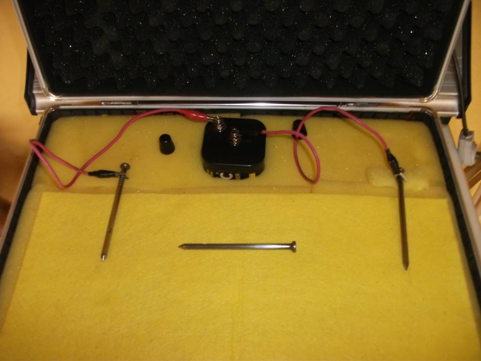
In order to keep it simple we must return to the three nails demonstration to understand what we can measure and what the data tells us.
Why is the three nails demonstration a game changer?
This simple experiment can be used to examin in detail the theory behind the measuring processes we use in cathodic protection field work.
It was recognised in the 1970s that the criterion was in error and pipeline operators investigated the reason why leaks were occurring in places that had been regarded as protected
Field engineers simply believed what their clients specified and the pipeline owners contracted others to apply the science that had satisfied the theories in laboratory experiments. So science was of secondary importance to money.
The 'three nails demonstration' is a simple demonstration of scientific facts
It is clearly seen from the above information that the term half-cell reaction was wrongly taken to infer that you could make a half-cell and use it as a reference against which you can measure another potential.
In fact the half-cell reaction can only be created in controlled circumstances in a closed circuit measurement condition and the demonstration (involving the three nails) proves conclusively that you cannot do this in field work.
Present field practices.
Over the past five decades pipelines continued to fail due to corrosion that continues because of measurement errors and the pipeline owners engage consultants who confirmed that the copper/copper-sulphate electrode is acceptable as a reference.
The corrosion control industry has confirmed that the measurement should be taken using a standard reference electrode and nobody could understand what was wrong.
Field engineers teach cathodic protection technicians, who in turn form their own service companies, who continued using similar techniques.
A more scientific approach was required.
Specialised equipment is used, world-wide, and is very efficient, but there are many disastrous failures, which could be prevented by proper measurement of the corrosion voltages. This has been recognised by NACE and ISO and many people in the industry, but they have not presented a solution to the problem.
I recognised the error within 20 minutes of being shown how the measurement is made but it took me some months to find our how to accommodate this understanding within the work that I was being paid to carry out.

It took me a couple of years to realise that a solution to this problem had to be devised or corrosion will never be controlled by applied cathodic protection.
In medical science it is common practice to experiment with cultures of the bacteria and samples of the virus that is causing the trouble and it was apparent that we needed a corrosion cell that we can measure and control so that we can see the success of our work.
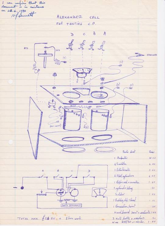
The original design for the Alexander Cell (corrosion cell)
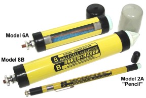
The general purpose Alexander (corrosion) Cell
The criterion for achieving cathodic protection is widely accepted to be a voltage measurement that is supposed to indicate an equilibrium between the metal and the electrolyte at which no metal is going into solution. We can see that no corrosion is taking place in the Alexander Cell because the electrochemical reaction has been halted. Farraday said that the amount of metal going into solution is proportional to the current passing from the metal into the electrolyte.
Copper/copper-sulphate electrode is NOT a reference potential when used in the way we try to use it in the field
We can see this because of the displayed voltages as we apply this reasoning to the demonstration involving the corrosion of three nails.
Visible corrosion
This criterion has been under continuous review for at least 50 years, that I know of, and there is still no advice that is backed by demonstrable evidence, published by NACE, ISO or any of the corrosion control institutions of which I am aware.
In the 1980s the Alexander Cell was suggested to the National Physical Laboratory in the UK but they were told of an arrangement of coupons that is NOT the one that I invented.
I presented the Alexander Cell to the Institute of Corrosion Science and Technology in London in the mid 1980s and this was published in two international journals specialising in corrosion control and pipeline management.
When I personally submitted the Alexander cell for examination by The National Physical Laboratory in the UK they dismissed the idea as "unnecessary, due to the satisfactory performance of existing practices".
They made a report that they sent to specialists in corrosion control. The Chairman of the British Standards Institute committee for Cathodic Protection, Jim Gosden, officially demanded that the report be withdrawn and highlighted no fewer than 17 gross scientific miss-statements.
The measurement of actual corrosion in field work.
This did not prevent the report being sent to Libya where it misled Sirte Oil company into putting a major contract on hold.
There were many other well documented instances of disinformation to suppress the use of the Alexander Cell and thus prevent proper scientific measurement of the corrosion reaction in the field.
However, Alexander Cell has now been extensively field trialled and in 2009 I made presentations at two international conferences in Brazil, announcing it as a definitive criterion for cathodic protection.
Using ORAC 2 as a test bed, you will see that this is illogical thinking that has never been supported by science but is used as the basis of all cathodic protection design, monitoring and maintenance at this time.
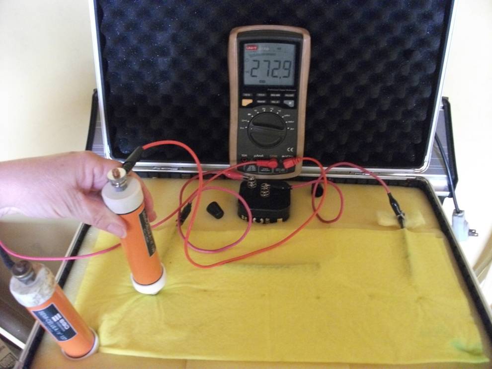
The picture below is of a demonstration piece called ORAC 2.
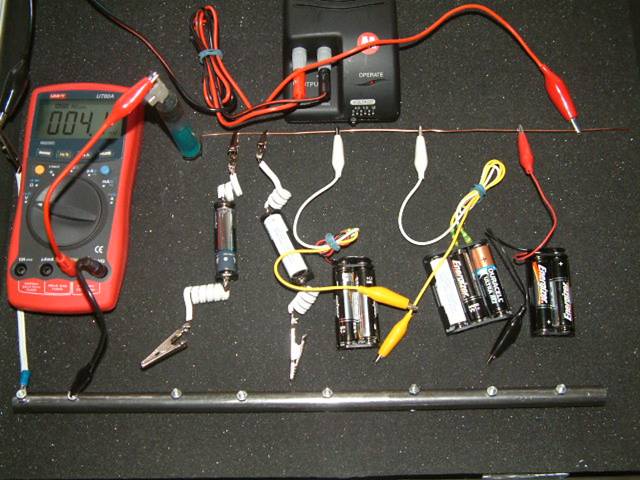
Orac 2
This arrangement of dry cell batteries is similar to the arrangement of corrosion cells that confronts us every day on pipeline networks. We use a system of measurement called pipe-to-soil potential measurement that is a really a voltage obtained using a voltmeter or oscilloscope. The measuring circuit is completed by touching the ground with a copper/copper-sulphate electrode.
The 'ground' in this model is a copper wire that is connected tp the positive + of the DC power supply.
The pipe is seen to be a short length of steel pipe fitted with bolts to connect the croc clips. This is connected to the negative connection of the DC power supply.
Using ORAC 2, we can represent this part of the measuring circuit by putting a new battery (of known value) in a battery holder with a depleted battery (in series) and measuring the total voltage.
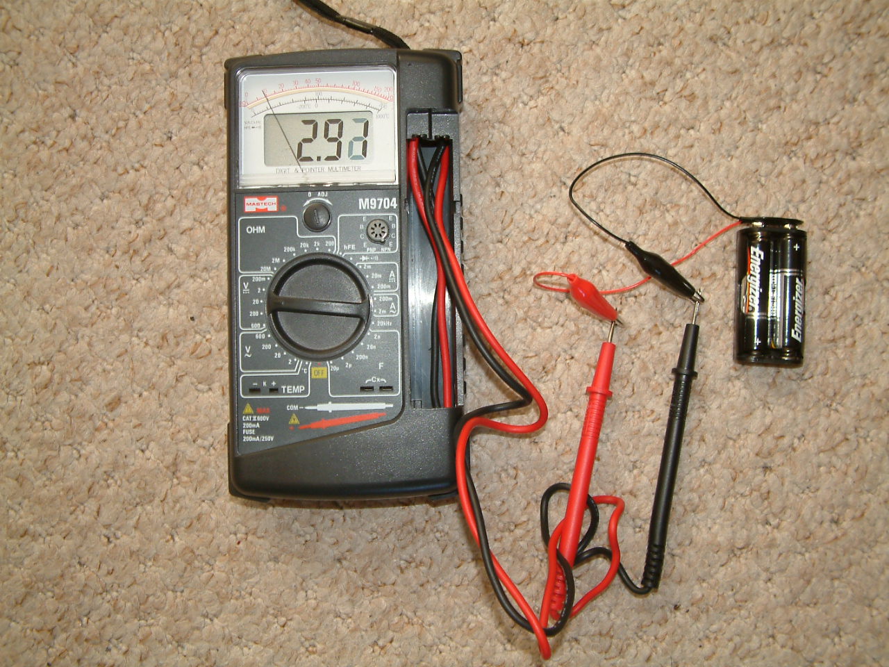
We then subtract the known value and discover the value of the depleted battery.
In closed circuit measuring conditions we can use this measurement to determine when corrosion has stopped and it is that reasoning that is behind the use of the pipe-to-soil potential as a standard criterion for the achievement of protection in the corrosion control industry.
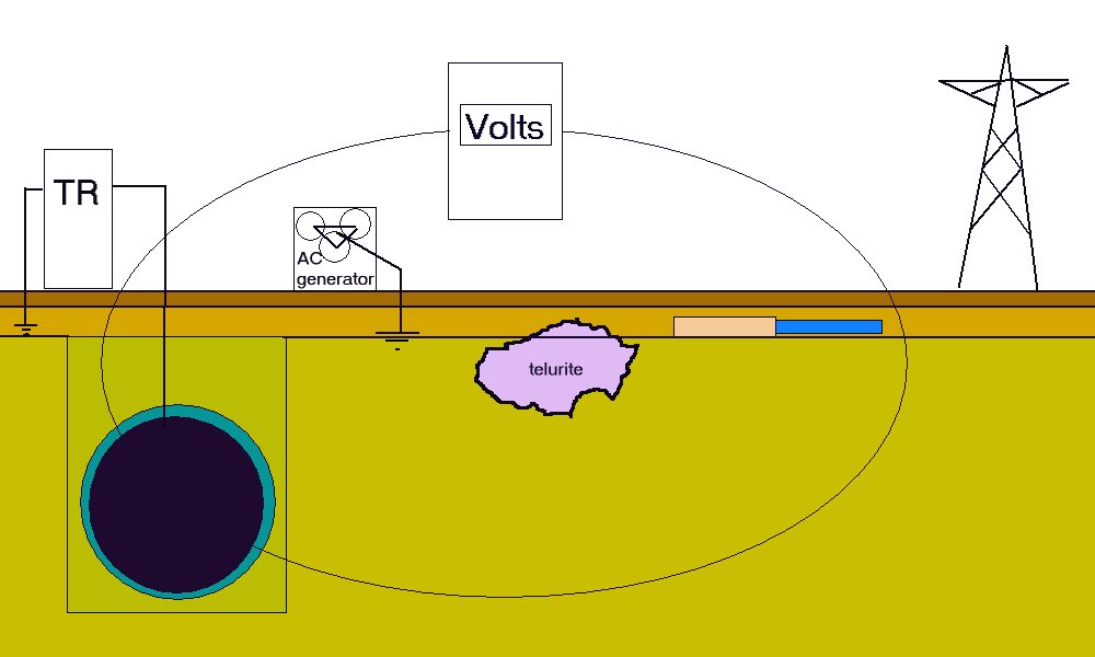
The whole world is a cathodic protection circuit.