PROCEDURE 8
Measuring and plotting the IR drop in the soil
caused by the groundbed of an impressed
current cathodic protection system.
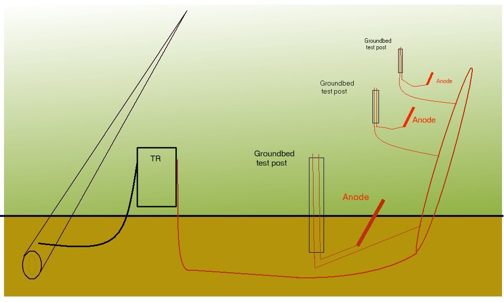
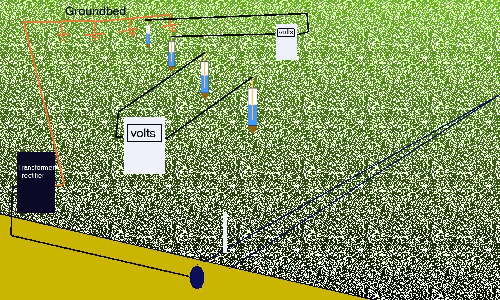
A cathodic protection groundbed is the connection between the DC positive conductor and 'mass earth'. Groundbeds are designed to produce a low resistance path, consisting of cable, anodes, coke-breeze and finally a large area of low resistance contact with mass earth.
The conductor carries the current from the transformer/rectifier to the anodes, and has a known resistance, which is calculated in the design of the installation.The anodes themselves have specified conductance properties as have the coke breeze and selective back-fill of the groundbed.
'Mass earth' is regarded as an infinite number of resistances in parallel, and therefore (Kirchoffs Law) has an infinitely low resistance.
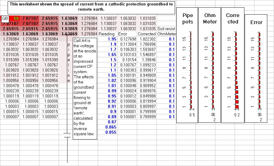
The contact between the groundbed back-fill and 'mass earth' has a finite resistance which decreases as the current moves from the anodes, and it is this resistance which is the R in the IR drop that we seek to define by this procedure.
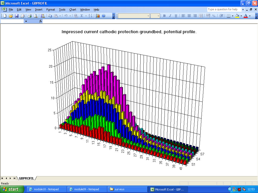
This can be plotted as a 3D graph.
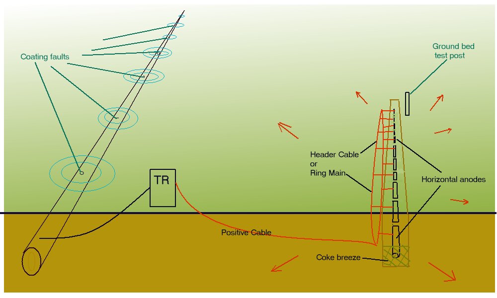
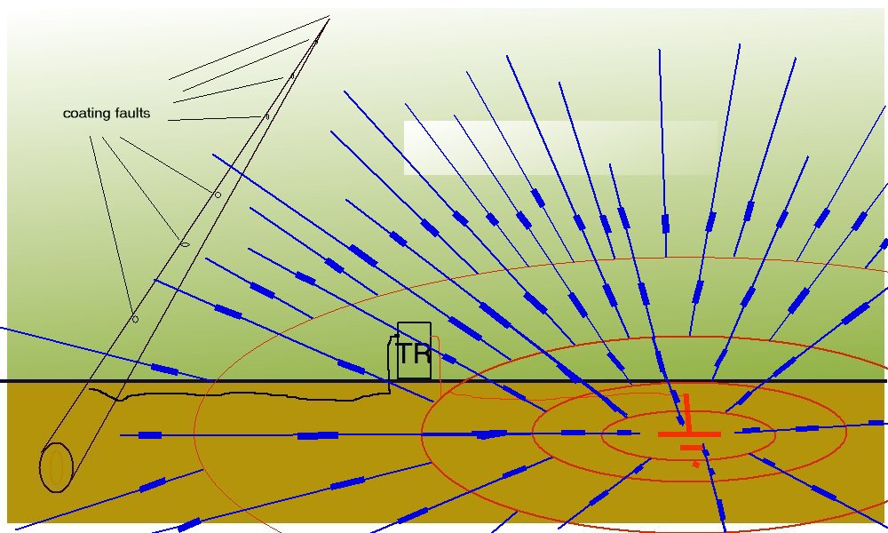
Problems are encountered in locations where there are no low resistance sites for the groundbed.In high resistance ground, high voltages are required to produce sufficient current output, and the ground close to the anodes develops an IR drop which can spread for several hundred meters before reaching "mass earth' potential.
This IR drop can be as much as 1 volt per meter, and even 100 m away from the groundbed, can be 0.200v per meter.If this effect spreads over a pipeline, then it is essential that the coating is in perfect condition, otherwise it will be suggested that cathodic disbondment can occur at 'holidays' and a virtual short circuit will reduce the spread of cathodic protection to this immediate area.
This procedure will enable the engineer to detect and remedy this condition as well as assist in detecting interference and shielding.
INSTRUMENTS
- Recording voltmeter.
- 2 Cu/CuSO4 electrodes
- long trailing conductor.
METHOD
8.1 Remote earth should be established using Procedure 2.8.2.1 The remote reference electrode is then connected to the negative terminal of channel 1 of the recorder.
8.2.2 The roving electrode is connected to the positive terminal of the recorder via the trailing conductor.
8.2.3 The voltage recorder range should be set above the highest TR output setting and the chart paper trace range should be set to record from 0 to maximum of FSD. The paper speed should be set at 240 mm/hr.
8.2.4 The CP TR is switched on and the settings and output readings are noted. 8.2.5 The roving electrode is then used as an earth contact probe to ascertain a starting point for the first survey. It is moved in line with the longitudinal axis of the groundbed to find a location where it produces 0 volts with respect to the remote reference electrode.
8.2.6 The chart is then marked"Longitudinal GB survey, location"
8.2.7 The roving electrode is then stepped at 1m intervals along the line of the groundbed while the voltages are watched by an assistant.. The chart trace will appear as a 'saw tooth' with the peaks showing the position of each ground contact. The locations of the highest peaks should be pegged on the ground as these are directly above the anodes. This survey should continue until the chart trace levels out.
8.2.8 The highest voltage point should be marked with a peg and will be used as the centre start for the remaining surveys in this procedure.
8.3.1 The chart paper should be marked "Transverse GB survey1"
8.3.2 The roving electrode should then be stepped at 1m intervals away from the centre start at right angles to the longitudinal axis of the groundbed.
8.3.3 This should extend until the voltages level out.
8.3.4 The chart paper should be marked "Transverse GB survey 2"
8.3.5 The roving electrode is then returned to the centre start and stepped out in the opposite direction until the voltages level out. The voltages recorded then represent a right angled cross over the groundbed.
8.4.1 The chart paper should be marked "Max TR output 'n' volts 'n' amps
8.4.2 The TR should then be set at maximum output.
8.4.3 Procedure 8.2.5 to 8.3.5 is then repeated.
8.5.1 The chart paper should be marked "50% TR output 'n' volts 'n' amps."
8.5.2 The TR should then be set at exactly 50% of the maximum voltage.
Procedure 8.4.2 to 8.4.3 is then repeated.
INTERPRETATION
The results will tell the engineer the effect of adjustment and whether this will bring the immediate GB influence over the protected pipelines. If this is the case, then a coating survey will be necessary to ensure that the short circuit does not limit the benefits of the increased output and introduce the risk of cathodic disbondment.
The voltages plotted are between two points in the ground, through electrodes with an internationally accepted standard reaction. Procedure 2 has ensured that the static remote reference electrode can be regarded as a fixed potential and the volts/distance plots are attributable to the current passing from the anodes through the resistant shells of ground surrounding the GB.
If the pipeline or other conductive path is available in one of these definable shells, the current will pass in inverse proportion to the resistances (Kirchoff) thus starving remote earth of a proportion of the output.
If the conductive path is connected to the negative terminal of the TR (for example, a coating fault or metal object touching the pipeline) a great deal of current will pass through it, causing a short circuit. This excess current can caused free hydrogen migration to the metal surface which will disbond the coating material close to the coating fault.
If the conductive path is not connected to the negative terminal but itself passes through a low resistance electrolyte, it could be subject to interference corrosion at any coating faults in that electrolyte. The groundbed profile will reflect this loss of current by a depression in the area at which the 'foreign metal' is picking up. It is also possible to trace the point of discharge of this current by interference testing procedures.
Most pipelines are part of a network of insulated conductors passing through a common electrolyte of variable resistance. The balancing of the electrical equilibrium of this network is essential to ensure that current does not stray from one section of the network to another via coating faults or unplanned paths.
click to return to procedures index page