INSTRUMENTS
- High resistance voltmeter.
- 2 Cu/CuSO4 electrodes.
- Trailing conductor reel and mounting.
Introduction
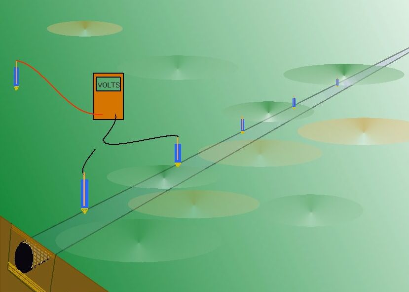
This survey plots the potential of the ground with reference to the potential of the ground at another location.
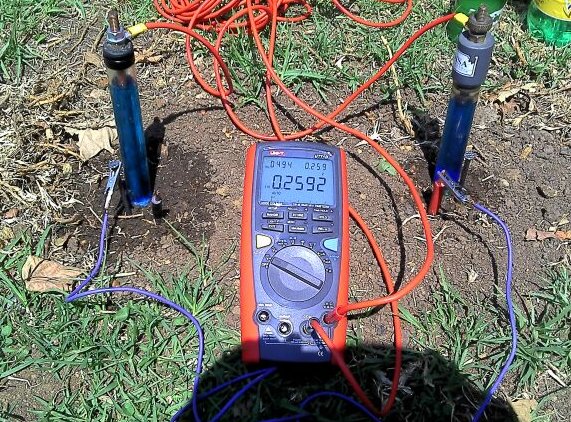
The measurements are volts which is the potential difference between the two poles of the meter or data logger.
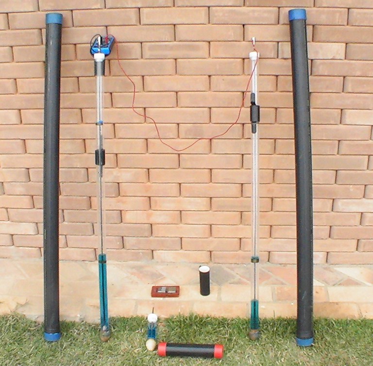
These pictures show a half-cell in a fixed location and another over the pipeline.
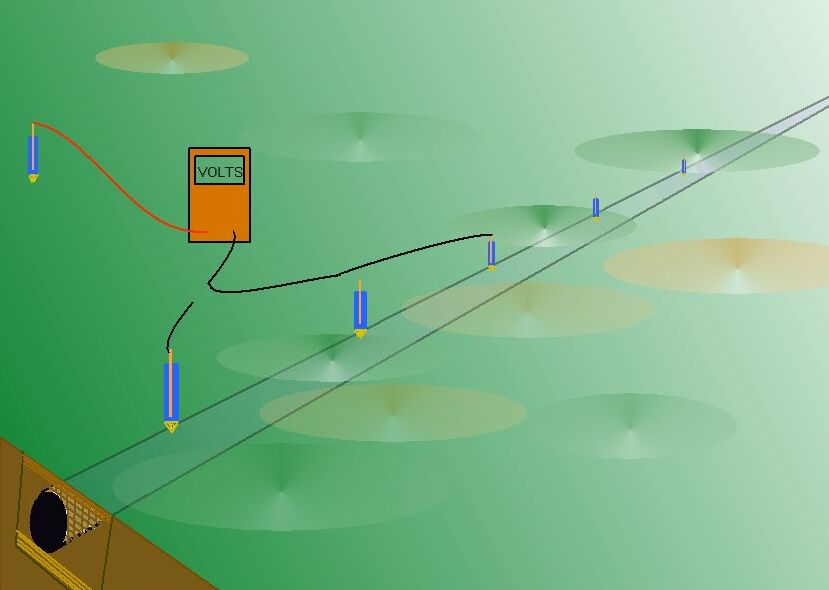
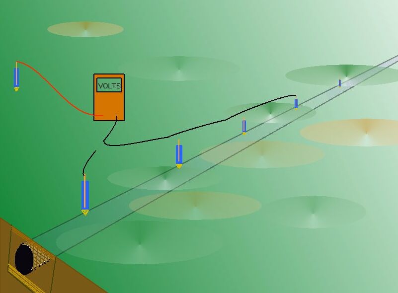
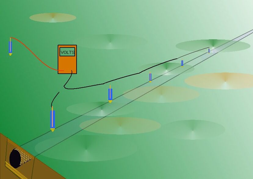
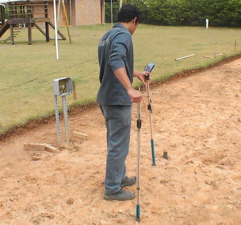
The next picture shows the half-cell over the pipeline being moved to a different location.
You will notice that the voltage changes with each new location.
This is due to the differing potential of the ground in which the 'roving half-cell' is placed.
We do not know the reason for these ground potentials and there is no way that the meter can tell us.
If we switch the cathodic protection current on and off at known intervals we can record the differing voltages that this caused to our meter.
DCVG Direct Current Voltage Gradient.
This survey plots the ground potentials between two probes that can be likened to half-cells as they consist of copper and copper-sulphate solution at some part of their measuring circuit.
The meter that is used can be a sensitive dampenned analogue current meter or a digital volt meter with recording abilities.
In this type of survey the two half-cells are stepped over the ground over the pipeline and the deflection of the meter needle or the variation of the voltage is seen or recorded by the operator.
As the survey progresses the ground potentials change with the cathodic protection switching and the natural variations in the ground potential.
METHOD
4.1.1. Use Procedure 2 to establish remote reference electrode.
4.1.2. Turn the cathodic protection installation to its normal operating mode.(on)
4.2.1. Connect the fixed, reference electrode to the positive pole of the high resistance voltmeter in such a way that this half-cell is immobile during the survey.
4.2.2. Connect the roving electrode to the negative pole of the high resistance voltmeter.
4.2.3. Unreel the conductor to the required starting position of the overline survey and again secure. The trailing conductor should then be free to play out as the survey progresses.
4.3.1. Contact the ground with the roving electrode, at one meter intervals along the path of the pipeline, noting the voltage readings between the electrodes, at each step.4.3.2. The locations of highest voltage should be marked.
4.4.1 When the required section of pipeline has been surveyed, the roving electrode should be stepped across the pipeline route at the locations of highest voltage.
4.4.2. These 'transverse' readings should extend as far as possible, or from "remote earth" to "remote earth".
INTERPRETATION
The largest voltages are obtained where the IR drop in the soil is caused by the CP current returning to the pipeline. It follows that the marked locations are over coating faults which allow contact between the backfill and the pipe metal.
It has been found that transverse readings can indicate the severity of the coating fault and help to eliminate errors caused by other IR drops.
click to return to procedures index page