
Cathodic Protection Training Course
Module 8
Spread of protective currents
Cathodic protection current is governed by the laws of electricity.
The measurement of the spread of cathodic protection currents is outside of the practices of the electrical and electronics industries because they do not have to deal with 'open circuit' measurements.
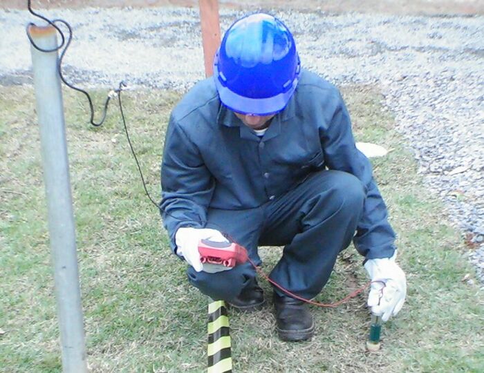
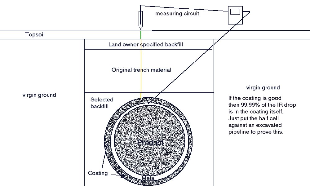
The term 'open circuit measurements' is used by Dr Peabody in a paper published by NACE to mean a measurement that is made between the metal of a structure or pipeline and a probe placed in the electrolyte in which the subject metal is submerged.
cathodic protection engineers are making such measurements as part of their field work and need to understand that there are only two values that they can possibly obtain.
One is the voltage between two variable potentials and the other is the amount of current flowing through the meter due to the difference in potential between the two poles of the meter that they are using.
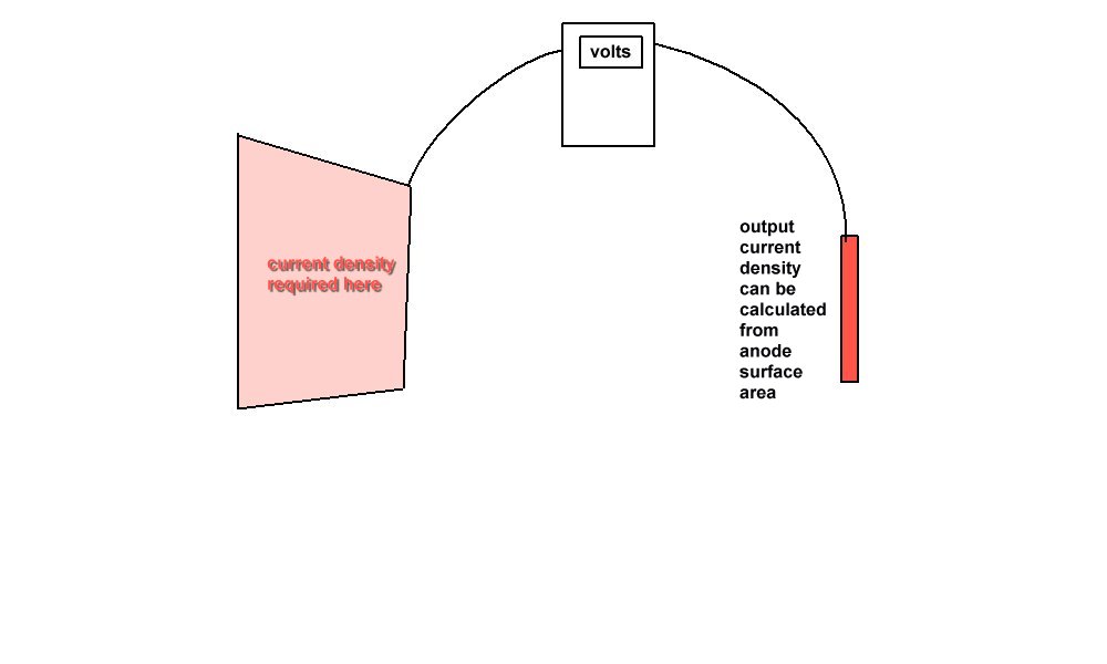
The term 'current density' is used by cathodic protection engineers to define the charge density in a particular area where the charges pass from the electrolyte into the subject metal. This might be possible if electricity followed straight lines like photons do in light diffusion, but it is not like that.
Charges diffuse three dimensionally and the whole universe reaches equilibrium with charges transfering to all particles around them.
It might be possible to calculate the current output density from an impressed current or sacrificial anode as the surface area can be measured but it is impossible to make even an informed guess at the current density required to cause any change in the corrosion status of any of the subject metal, except by using the Alexander Cell
If we want to be taken seriously by electrical and electronic engineers then we must deal in measurements obtainable using equipment and instruments that are acceptable in science. I know of no instrument that measures current density... and don't mention the induction loop ... that measures current.
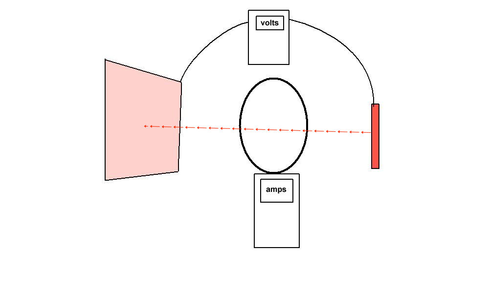
The current must pass directionally through the loop to induce charges that can be measured. Charges passing outside of the loop will not be accurately measured although they do affect the readings in my own experience.
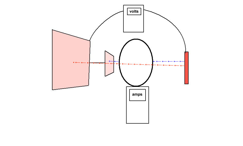
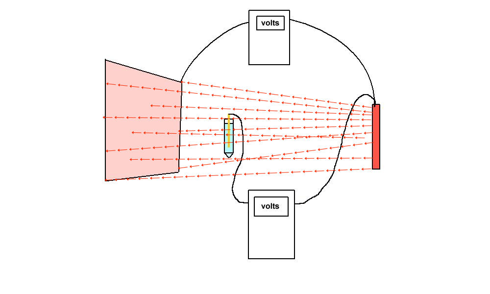
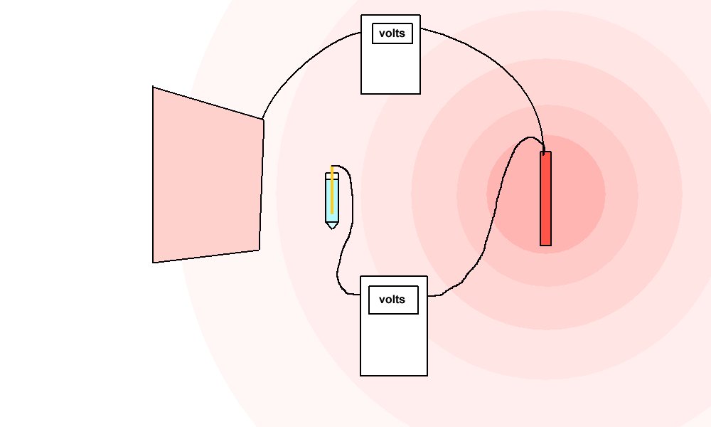
Kirchoff made it clear that charges pass from high potential to low potential through the least line of resistance in inverse proportion to the resistances in parallel. From this we can calculate that charges radiate out from a central source such as an impressed current anode according to the inverse square law of radiation until there is a difference in the resistance values they encounter.
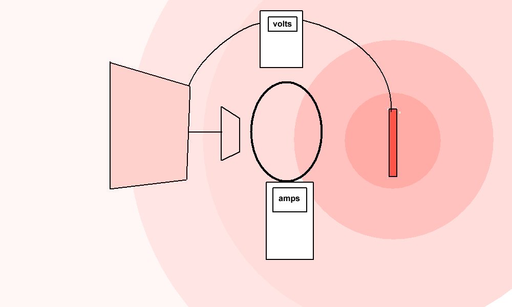
If there are high resistance boundaries to their path the current becomes linear and can be measured by the electrical disturbance it causes... therefore the induction loop is possible.
If a ground bed earthing facility is in a depression filled with conductive material but surrounded completely with highly resistant terrain, then it is possible that the immediate area is highly charged and the effects of the current may be seen on a potential profile extending many hundreds of meters.
A low resistance path such as a fence or a stream containing disolved minerals that passes both the immediate area of influence of the groundbed and coating weaknesses in a pipeline will offer a less resistant path to complete the cathodic protection circuit.
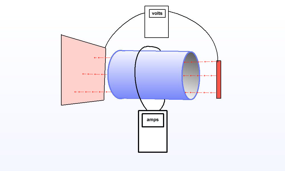
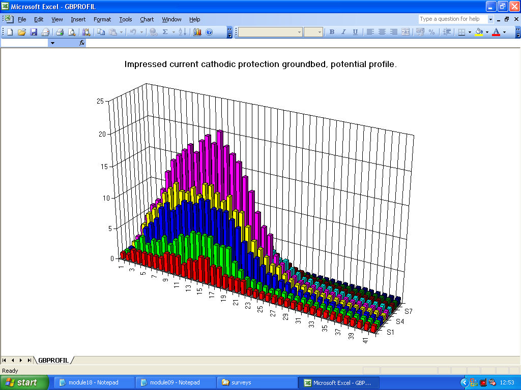
Such a condition is easily definable using a fixed ground contact probe such as a Cu/CuSO4 electrode and a roving Cu/CuSO4 electrode across a recording voltmeter or data-logger. This procedure will render a three dimensional graph depicting the ground potential profile and will clear show the density of charges in relation to the fixed probe.
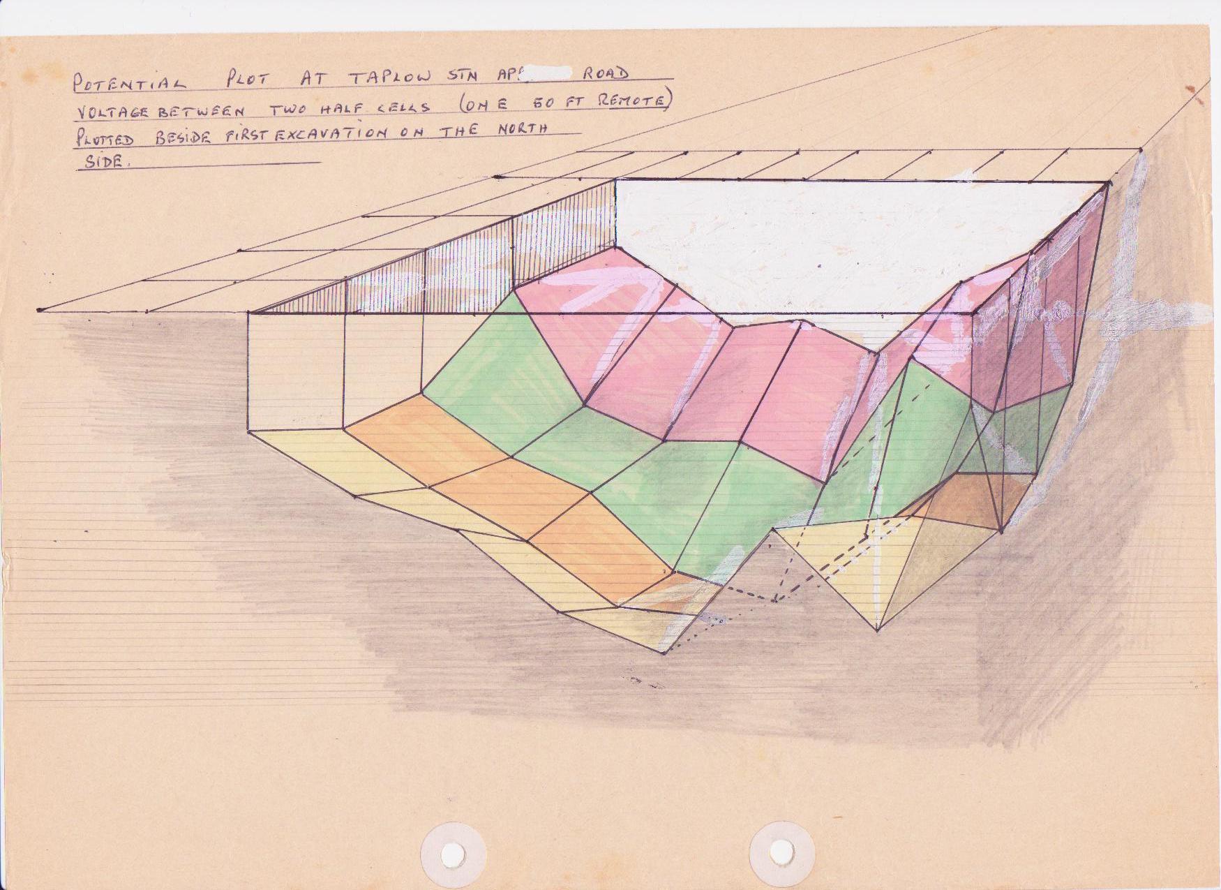
It follows that we must eliminate temporal flux in the subject area by relating all voltages to a fixed Cu/CuSO4 electrode diagonally opposite to the main fixed probe. This requires a three channel data-logger or two synchronised two channel loggers.
A cathodic protection field engineer must be familiar with these types of surveys if they are to obtain data that can be analysed and computed. These procedures also give the ability to visualise cathodic protection in it's entirety.
The established practices of producing 'attenuation curves' are of not help unless the data is analysed in recognition that the half-cell is not a 'reference electrode' and cannot provide the baseline that is proposed in such surveys.
This is the reason why so many Cathodic Protection system designs do not function in the way that they were designed.
Established codes of practice demand an assortment of criteria from a 'potential shift' to a 'pipe-to soil voltage with the CP current switched off' . For these purposes the zero in all calculations and graphic displays is the potential of the half-cell. The data that is obtained is in volts..... i.e. potential differences.
An attentuation curve assumes that the voltage rendered at each touch of the half-cell is due to the influence on the ground of the Cathodic protection system. By taking these measurements with the system switching on and off it is supposed that the IR drop in the soil is eliminated.
However there are many causes of electrical flux in the soil and water that are not eliminated and some of these affect the pipeline corrosion status and some of them only affect the reading on the measuring instrument.
It is for this reason that CPN procedures are so important to gather enough data to exctrapolate the value we can base our calculations on.
The spread of current from any single Cathodic Protection Transformer Rectifier can only be measured once the system is fully installed and commissioned. It is no good sticking in a temporary groundbed and doing a survey..... that is a waste of time, effort and materials.
The site of any impressed current groundbed must be in 'remote earth' so that the current does not have a preferential path directly to the pipeline metal.
The groundbed should be in low resistance ground and the four pin method of measuring the ohm/meter value has proved adequate to ensure that the TR can impress sufficient current with as low voltage as possible.
Groundbed sites sre normally not found on land owned by pipeline operating companies and so it is suggested that a temperory groundbed is set up in the proposed area and a groundbed potential profile is plotted (CPN Procedure 8) to ensure that the immediate area of influence does not overlap the pipeline wayleave.
An overview should be mapped and any likely low resistance ground paths should be marked and tested. This could be stream carrying waste and structures that might have underground services connected. Roads, canals and railways should be marked and tested.
It should be remembered that we are not testing for stray currents or interference at this stage of events.... simply for low resistant current paths from our own groundbed. We can therefore gather data resulting from switching our own TR. and measuring the shift in the potential of the soil relative to remote earth.
This is done using the two-half cell survey as described in CPN Procedure 2
Back to Module08 index page