Cathodic Protection Training Course
Module 8
Ground resistivity instruments
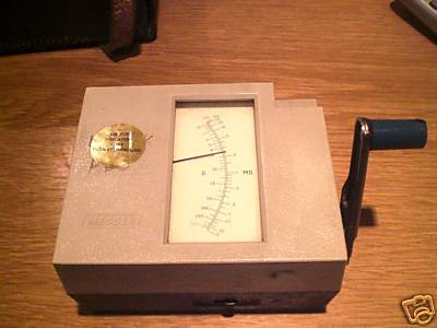
The Megger
The megger is a portable instrument used to measure insulation resistance. The megger consists of a hand-driven DC generator and a direct reading ohm meter. A simplified circuit diagram of the instrument is shown in below.
The moving element of the ohm meter consists of two coils, A and B, which are rigidly mounted to a pivoted central shaft and are free to rotate over a C-shaped core. These coils are connected by means of flexible leads. The moving element may point in any meter position when the generator is not in operation.
As current provided by the hand-driven generator flows through Coil B, the coil will tend to set itself at right angles to the field of the permanent magnet. With the test terminals open, giving an infinite resistance, no current flows in Coil A. Thereby, Coil B will govern the motion of the rotating element, causing it to move to the extreme counter-clockwise position, which is marked as infinite resistance.
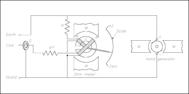
Simple Megger Circuit Diagram
Coil A is wound in a manner to produce a clockwise torque on the moving element. With the terminals marked "line" and "earth" shorted, giving a zero resistance, the current flow through the Coil A is sufficient to produce enough torque to overcome the torque of Coil B. The pointer then moves to the extreme clockwise position, which is marked as zero resistance. Resistance (Rl) will protect Coil A from excessive current flow in this condition.
When an unknown resistance is connected across the test terminals, line and earth, the opposing torques of Coils A and B balance each other so that the instrument pointer comes to rest at some point on the scale. The scale is calibrated such that the pointer directly indicates the value of resistance being measured.
To measure it, the standard method that enjoys overwhelming acceptance is the Wenner method.
This is named for Dr. Frank Wenner of the U.S. Bureau of Standards, now known as the National Institute of Stan-dardsandTechnology(NIST),who developed it in 1915. The Wenner formula is:
? = 2pAR
where ? is average soil resistivity to a depth equal to A, normally expressed in ohm-centimeters,
Ais probe spacing, again normally in centimeters,
and R is the test instruments reading.
It is fairly simple to make this reading.
The basic requirement is to have a four-terminal tester.
Some simpler models have a com-mon terminal in place of one pair of separate voltage and current terminals.
This configuration is adequate for testing resistance of installed grounds, but to perform Table 2 Effect of Salt Content on Soil ResistivityFor Sandy Loam, 15.2% MoistureSalt ContentResistivity, Ohm-CmNo Salt Added10,7001.0% Salt Added46020.0% Salt Added100the Wenner method (and various derivatives) the full four terminals are a must.
These are connected by leads to four metal probes driven into the soil with equal spacing.
This horizontal spacing on the surface is determined by and is equal to the depth to which the soil is to be measured.
Probes are driven to one twentieth (1/20) of the horizontal spacing (Figure 1). The tester is energized, the reading taken, and the calculation performed.
This will yield average soil resistivity to a depth equal to the spacing at the midpoint of the four test probes.
For obvious reasons, the method is also frequently referred to as the four-point method. The industry standard unit of measurement is the ohm-centimeter, but other units of length may be substituted for special situations and will work just as well.
The ohm-centimeter is the unit that most often appears in tables of resistivities and is typically used for calculations of grid design.
Resistivity so calculated is also sometimes termed apparent resistivity, since the ideal model is based on soil homogeneity which is typically not the prevailing condition in the field.
Line Traverse
This data then has numerous valuable functions.
These include, but are not limited to, location, design, cathodic protection, and vertical prospecting.
A section of ground can be tested at regular spacing to cre-ate a contour map of resistivities across the entire area.
This procedure is called line traverse and is commonly used to locate the optimal site for a ground installation.
Low resistivity equals high conductivity, so this method will indicate the best spot to install a new ground electrode.
Line traverse can be performed relatively quickly and efficiently and is, therefore, superior to the arbitrary practice of driving individual rods and testing them for resistance.