Cathodic Protection Training Course
Module 8
Ground resistivities
Ground resistivities are very much misunderstood and should be addressed from scratch.
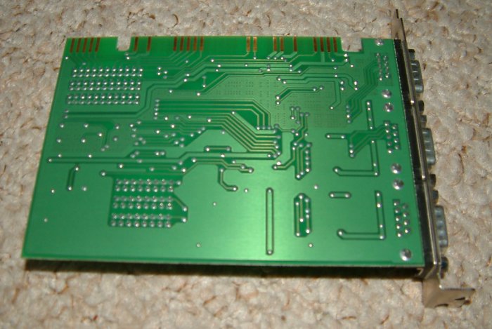
Regard the pipes as conductors set in a pcb (Printed Circuit Board) that is in fact the ground.
Unlike manufactured pcb's, we cannot control the resistivity/conductance of the material of which this giant circuit board is made.
A computer or television would not work if the pcb was made of clay, or lead, or a mixture of clay and iron ore.
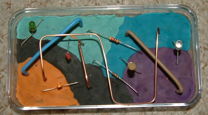
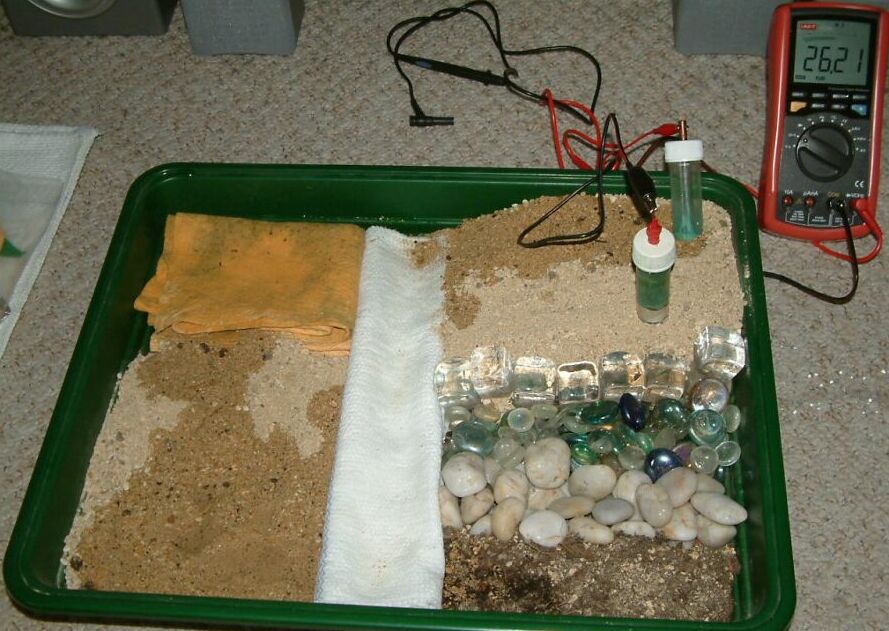
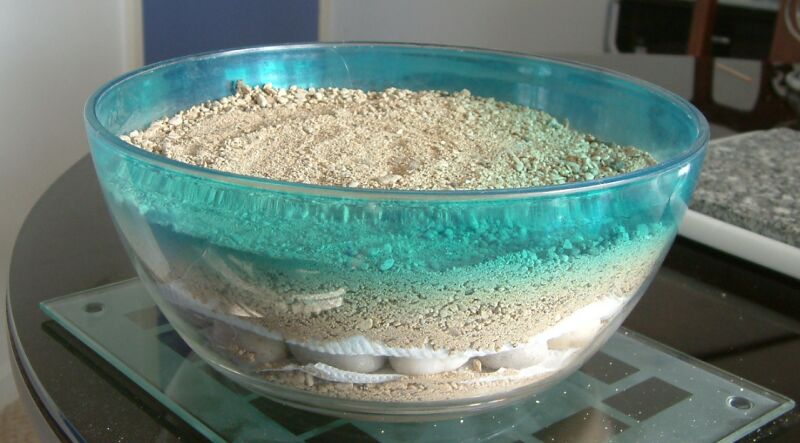
The model shown above is some electrical componenets stuck into a 'pcb' made of modelling clay of different colours.
This is a similar situation to that confronting a cathodic protection engineer. We are presented with the equivalent of electrical components embedded in an assortment of randomly arranged materiels of unknown composition. The dye in the modelling clay might (or might not) affect their properties of conductance.... we do not know.
A circuit analysis of all the cathodic protection systems can only be attempted if we carefully define all the components of that circuit including the conductance of the ground in which the pipelines are embedded.
So how do we get from the plasticine model to the manufactured pcb?
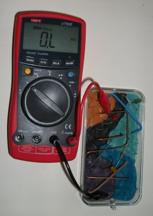
We must measure the resistance between each of the electrical entities on the board. We can do this with a multimeter that puts a known charge into one item and measures the charge that arrives at the other.
This is the simple application of Ohms law and it is that which is used in the two half cell survey and CIPS.
In the case of the manufactured PCB the board itself has an almost total resistance and we are able to implant components and conductors wherever we need to complete the circuit.
There are various resistance survey techniques that are commonly used in the CP industry and each has gross misconceptions at their basis. These are dealt with in the pages of this module.
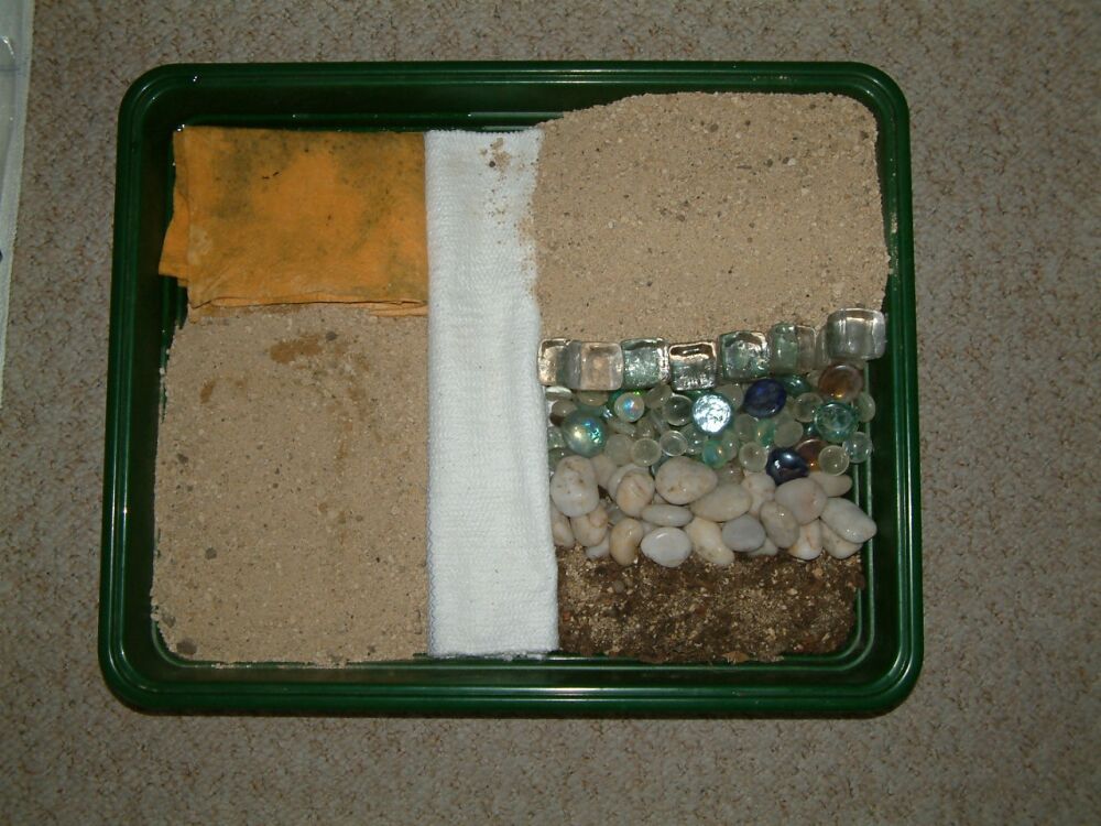
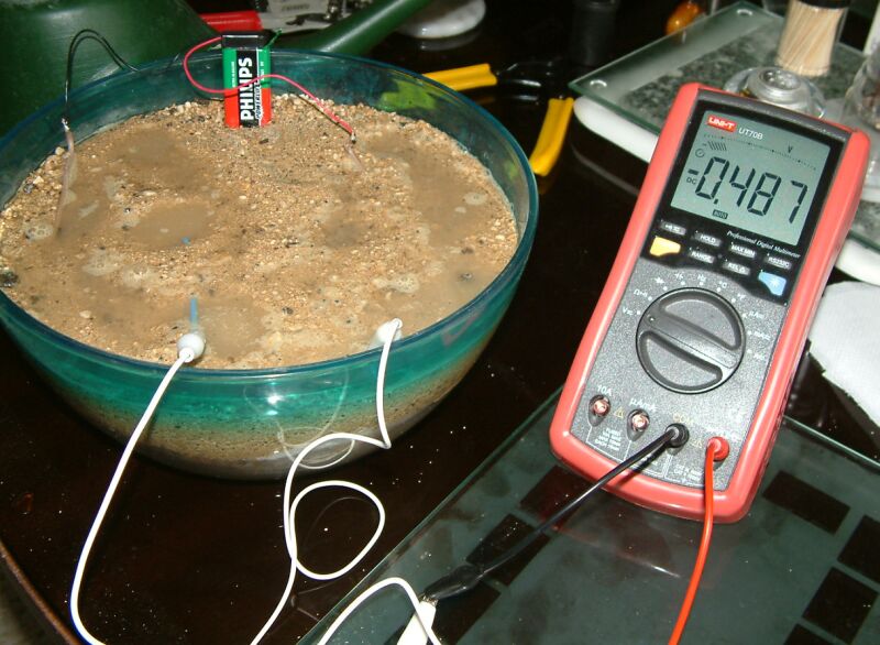
The best way to gain the practical 'feel' of the effect of ground resistivity is to make a bench model to study. This is very easy to do..... just a plastic tray with a variety of soils, sand, humous material and rock.
It is important to understand that this is a single, seperate circuit board and that we are striving to understand an intergrated circuit consisting of the whole world. The plastic tray makes it easier for the first stages of the study.
We can use this model to study the currents flowing in the immediate vicinity of a coating fault/corrosion cell as we have done in many bench experiments in this course, but in this instance we are studying the actual paths of the currents and the way that low resistance earth paths can effect the distribution of the beneficial effects of cathodic protection as well as the harmful effects of 'interference currents'.
Due to the confined nature of the currents we are using and the easily seen electrical paths we are creating, the resistance setting of a multi-meter is sufficient to allow us to make many studies.
The first thing to note is that the method of actually connecting the meter 'measuring circuit' to the subject conducting/resisting path is a component of the resulting measurement. It is for this reason that it is a good idea to have a standard contact area such as found at the porous plug at the bottom of a standard half-cell.
Unfortunately there are so few people in the CP industry that understand this principle that no manufacturer or standards organisation has bothered to standardise this!
However by the time you students have finished playing around and experimenting with this model you will understand the principle and be able to make extremely useful measurements in the field.
By this stage of the course you will have made your own half-cells and you should use these for experiments on this model.
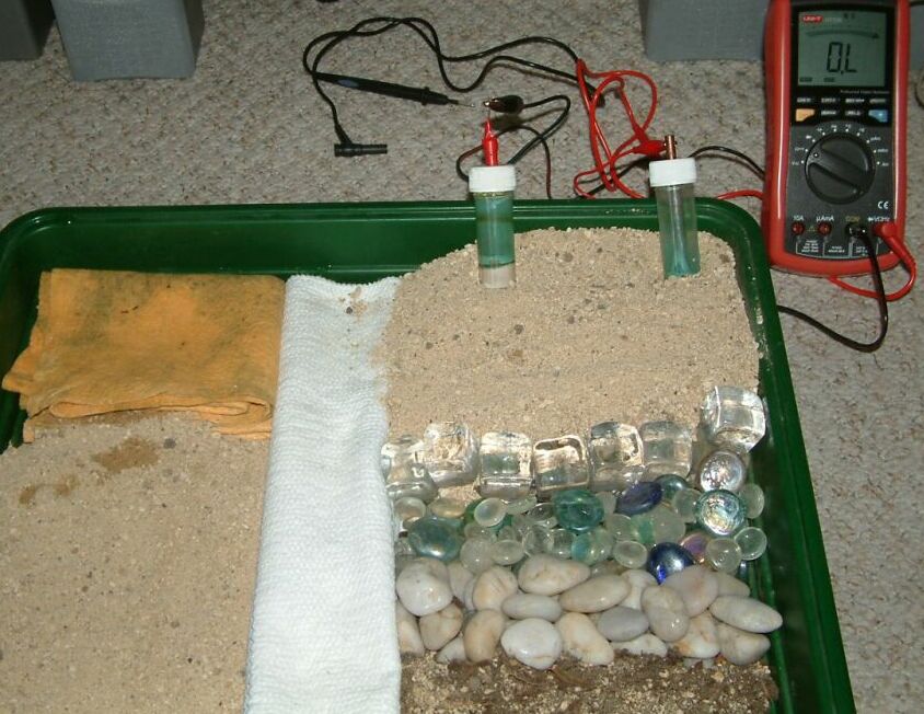
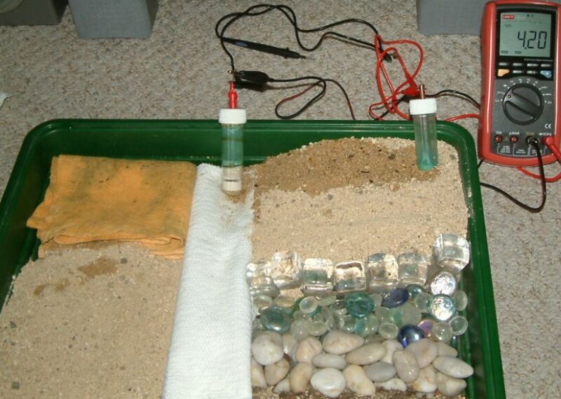
The pictures below show two half cells that would give the 'experts' nightmares and all sorts of excuses to condem data as unreliable and the operatives as incompetent. Forgive them, they simply do not understand!
The next series of pictures shows OHMs readings when the half cells are placed in a variety of positions on the model and when the various areas of the model have been damped with water and the with lemon juice.
Experimenting in this way will allow you to understand the effects on the spread of current on earth potentials and the resulting data gathered using CPN procedures.
You can carry out these experiments in the field close to a CP test post and you will find how the effects of omni-directional currents from remote earth create a slightly different picture than those in the confined area on the bench.
It is for this reason that there are two versions of the Alexander Cell...... the laboratory version and a variety of field versions. The laboratory version overcomes the errors created by the directional flow of current due to confined conductive paths.
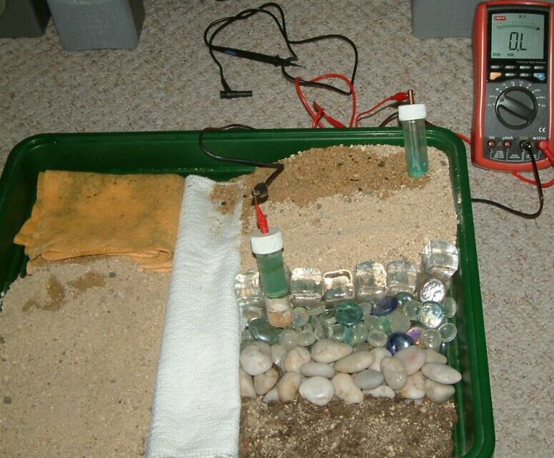
In the picture above you will note that the meter is reading OL..... overload. This means that there is not sufficient energy in the battery of the meter to force current through the resistance of the dry sand in which the half-cells are placed.
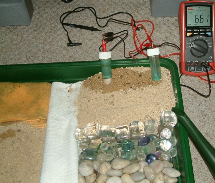
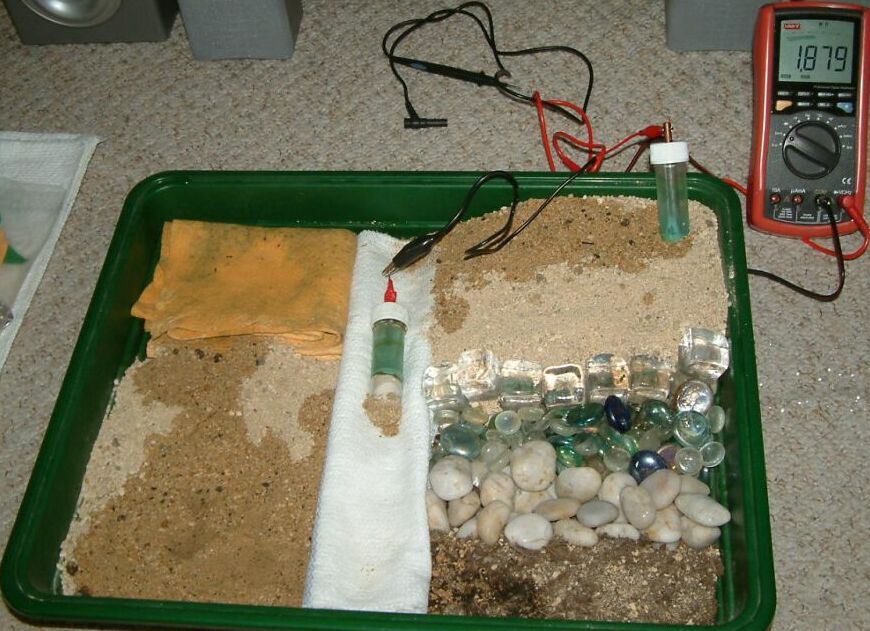
In the picture above, the sand between the half cells has been soaked with tap water. This will have three main functions in conductivity. It will physically improve contact between each particle of sand by actually moving them together. It will disolve the salts that are between the particles of sand and it will have salts from the tap water supply. Eletricity moves through disolved salts.... distilled water is very resistant.
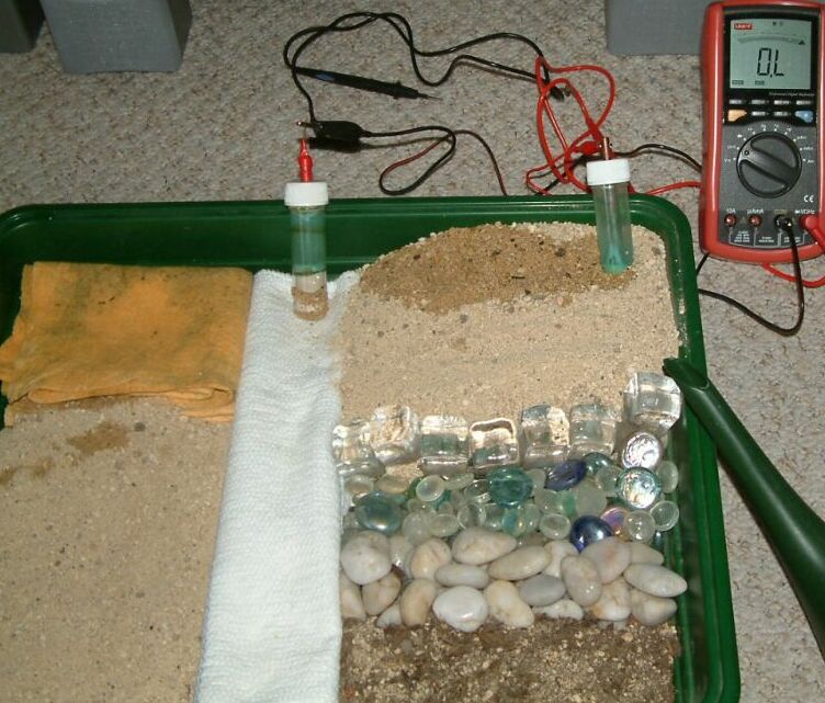
One half-cell has been moved onto the dry cloth and it can be seen that the meter is too feeble to force measurable current through the circuit.
More tap water has been poured and that has provided more conduction in two visible ways.... it has washed some wet sand onto the cloth and it has provided better contact between the fibres of the cloth.
The 'roving half-cell' has now been placed on the damp poluted 'super-absorbant cloth' and this has provided a better contact with the sand in the position of the fixed half-cell. It will be seen that the yellow cloth has a good area in contact with the white cloth and that has good contact with the damp sand.
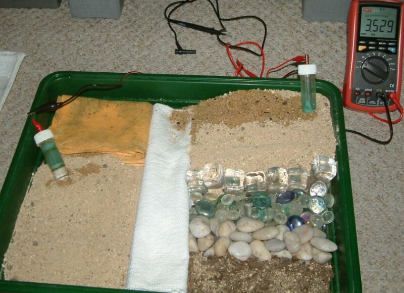
The roving half-cell is now in sand with added soil particles but this is still more resistant than the previous placement.
The roving half-cell is now on glass pebblesand they allow no passage of measuring current.
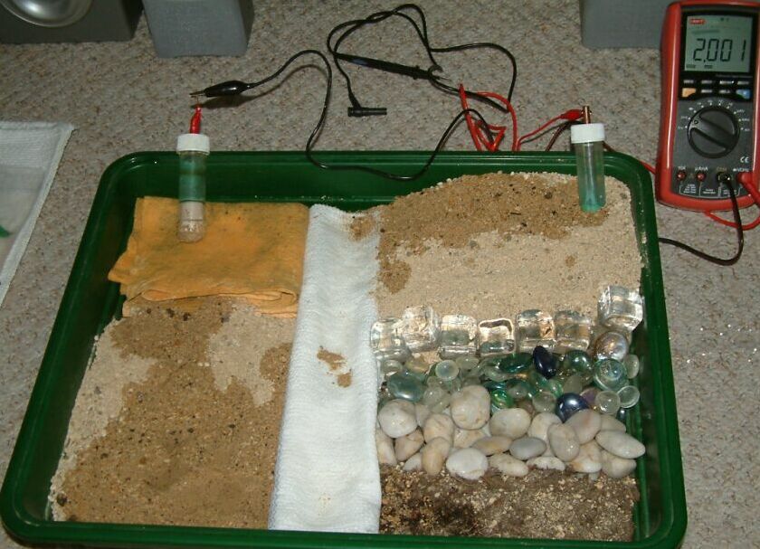
The roving half-cell is in sand and soil mix that should result in good electrical contact but it can be seen that the meter is still showing overload. The tray itself is non-conductive and there is an effective barrier of insulating materials in the path of the measuring current.
It can be seen that water has been added to an area in the sand but this has not changed the reading on the meter. There is still insufficient conduction between the two half-cells to allow a meter reading.
The white cloth has now been soaked in water but still there is no conduction.
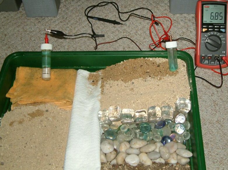
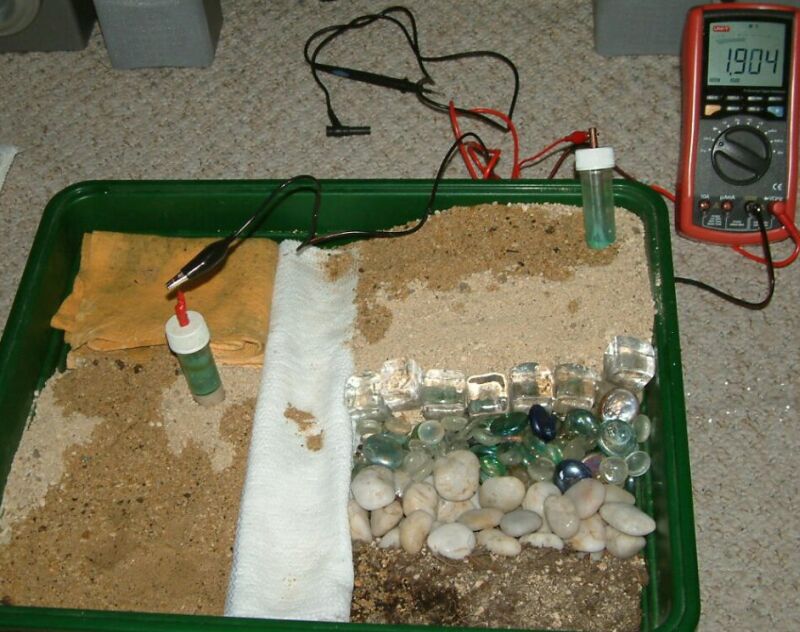
The gap has been bridged and the result can be seen on the meter.
The meter reading can be changed by adding more water, and will change itself as the water soaks in .... the equivalent to rainfall and tidal changes affecting pipeline corrosion.
the roving half cell is back on the glass and the meter is showing that this is stopping the measuring current.
It is placed on the pebbles that are now wet and the surrent is able to provide a resistance reading on the meter.
It is back on the glass but still no reading on the meter. This is what is found when placing a half-cell on dry concrete when conducting a CIPS or DCVG survey.
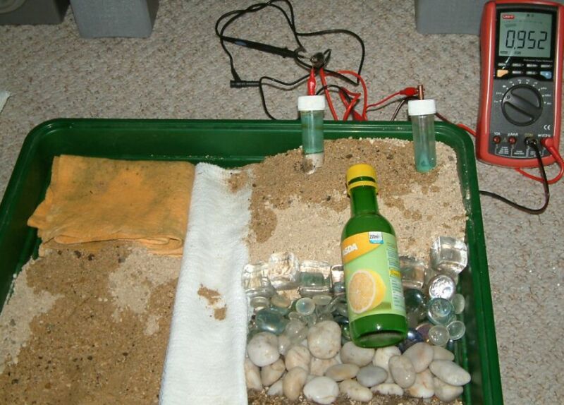
We now wet the glass pebbles and see that we have a reading. It is important to realise that this is a TOTAL RESISTANCE READING between the two points of ground contact. It is as a result of the passage of the current through all of the resistances in parallel... and this is how it must be computed in order to be relevant.
We can now use the model to see the effects of a variety of arrangements.
In real life, heavy rainfall can have the effect of washing the salts out of silican sand based soils and snow can insulate effectively. Frost, however can break up the structure of some rocks and do not forget that we are dealing with conductivity in three dimensions.
Most of the earth is in stratas and drilling with metal pipes connects layers of different conductivity.
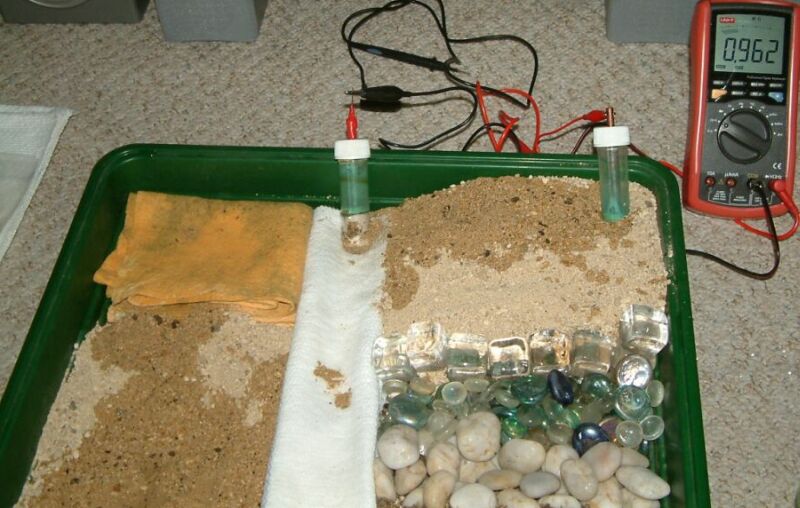
In these last two pictures we have used lemon juice to wet part of the circuit. In real life this type of situation arises where there is spillage of effluent, industrial waste discharge, animals or humans relieving themselves in concentrated areas and causing an increase in conductivity.
By this time you will have realised that measuring resistances in the field is almost impossible and that any results are of little scientific use.
However we must make some sort of gesture and get some information on which to base a standard design for a starter.
Back to Module08 index page