
Cathodic Protection Training Course
Module 5
Significance of the paper presented at the
Australasian Corrosion Conference of 1982

This paper was an attempt to address the problems inherent in the monitoring of cathodic protection.
It confirms everything found in field practice and was followed up by a book by the same authors. This book is in the library of UMIST and was lent to me for a short period by a student who attended a course I ran under the manpower services commission in the UK.
Unfortunately, the practices recommended in the book are very expensive as they required qualified engineers and a van load of instruments. I believe some surveys were carried out to these specifications but I have no knowledge of the effectiveness. I have not had the time or opportunity to research this matter but would be pleased to get any information from anyone.
Students should write their own version of this paper in their own words. This will be published on the CPN website together with my own version. The intention is to have everyone in the CPN 'singing to the same songsheet'.
The front page makes it clear that significant errors exist in the 'immediate off' voltage measurements that are still the mainstay of cathodic protection measurements.

These scientist have missed one practical point. Before the advent of digital multimeters there was a depression in the potential of the ground caused by the cathodic protection current that was necessary to drive the mechanism of the meter itself. This is described in detail in the Module dealing with instrumentation.
Up until the 1980's there was a huge effort to get the cathodic protection readings to a level that was virtually impossible. On the wide spread use of digital meters it was found that 'protected' readings were achievable at locations where they had been impossible. There is no way of establishing which of these measurements indicates the true achievement of cathodic protection.
The formulae above are a complex way of explaining that the voltage on the meter is the sum of several potentials. We need to know one of them to discover if the metal is corroding.

Now THAT page seems to me deliberately confusing. If you wade through the strange letters used to express quite ordinary things it is quite clear that there are a lot of approximations and uncertainties in the rational.
Read it again and again whilst visualising each symbol meaning something with which you are familiar. Question all assumptions that you do not regard as proven. In real life you will find that the voltage drops for days after switching off the TR. What the above formulae does not even consider is that we are dealing with an unknown number of corrosion cells in parallel. The Pourbaix diagrams make it plain that you must know the pH of the electrolyte to determine the value they describe as Ep. Do not let this sort of scientific expression cloud the issue. We need to know when the CP has stopped corrosion at each location.

The statement at the top of the above page is not correct in real life. Try it and see for yourself. I have ..... many times.

The above page has given a simplified equivalent circuit drawing of two coating faults. In fact there might be two corrosion cells on a single coating fault or a single corrosion cell consisting of an anode 500 meters from the cathode.

The page above shows 3 coating faults and makes assumptions that are not necessarily correct.

At this point of reasoning there is the assumption that 10 M perpendicular is not only remote from the influence of the pipeline

The page above shows 3 coating faults and makes assumptions that are not necessarily correct.
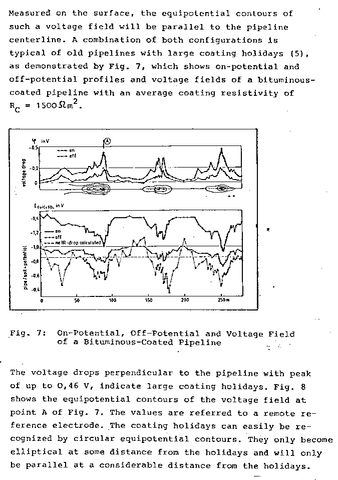
Students will now realise how the facts shown in Module01 are important when reading the above page.

It must be put into perspective that this paper quotes the results for surveys conducted over a very limited mileage of pipelines. The formulae rely on assumptions that can be questioned, if not rebutted.

The above page is very important as it says clearly that CIPS is useless. CPN Procedures are designed to overcome these problems and can render data that can be computer analysed including the effects of all electrical flux.

The above effects have been described as 'teluric effects..... this is a missnomer.

I was engaged by British Gas ERS to carry out the field tests in response to the studies of magnetic fluctuations and am very familiar with the results. It is quite amusing as I got the job as no-one else understood how to do it. They were all too busy using long words and spouting off at meetings.
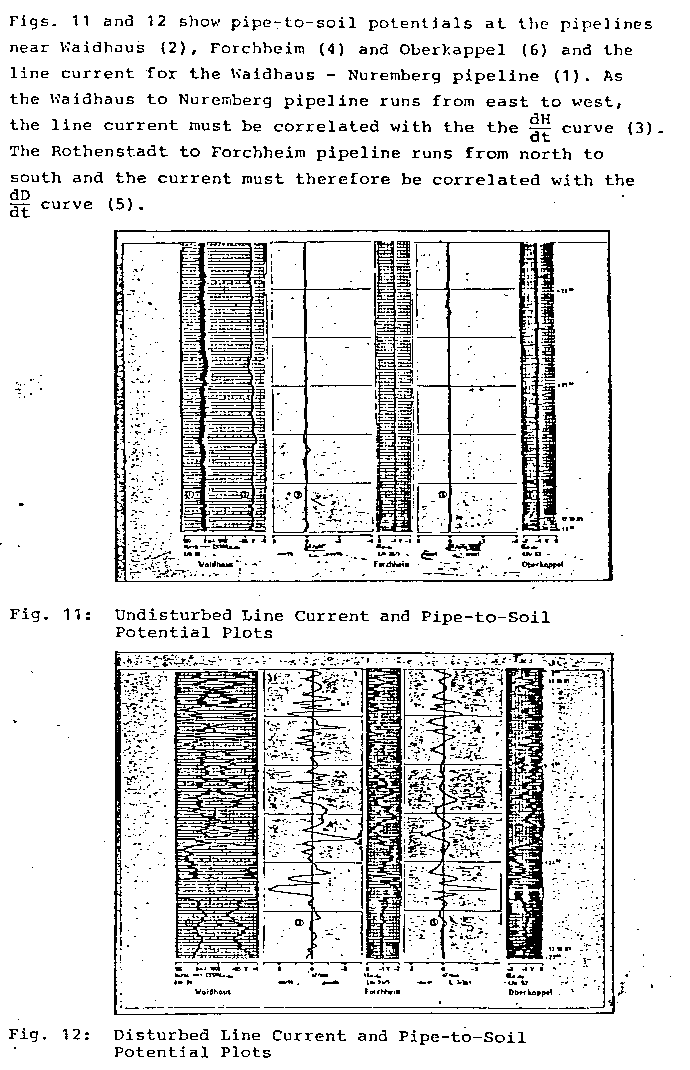
I have similar data and copies of chart recordings in the CPN archives.
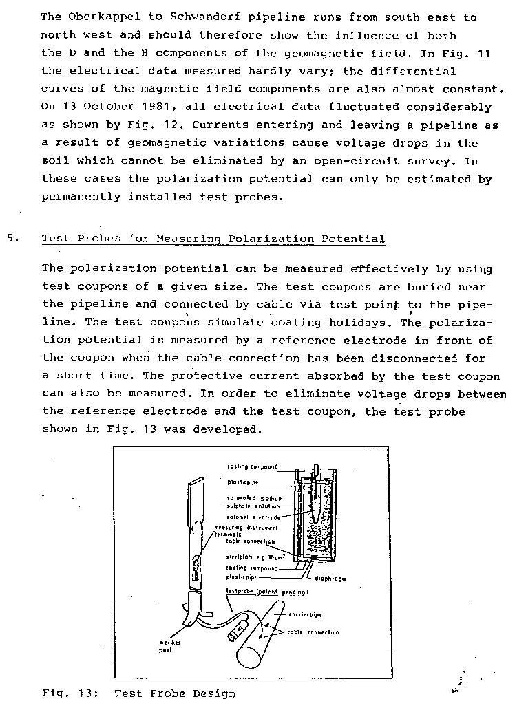
The above refers to a device that has since been patented individually by each of the authors. We can easily manufacture our own device called the Isopotential Cell and not be in breach of the patents.
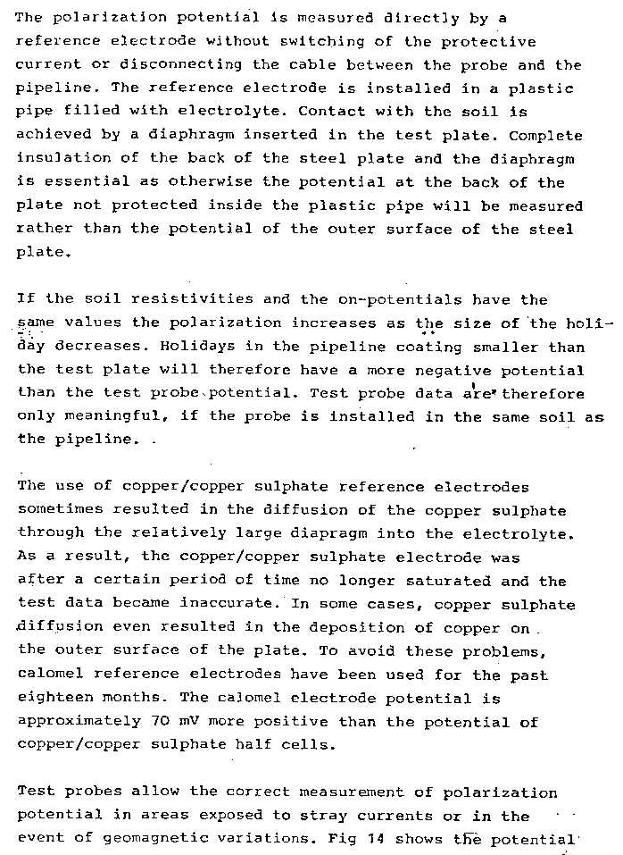
I have used isopotential cells in the field and in fact they have many problems other than those described above.

CPN have conducted the above tests in the field.
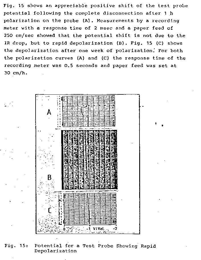
results available in the CPN archives
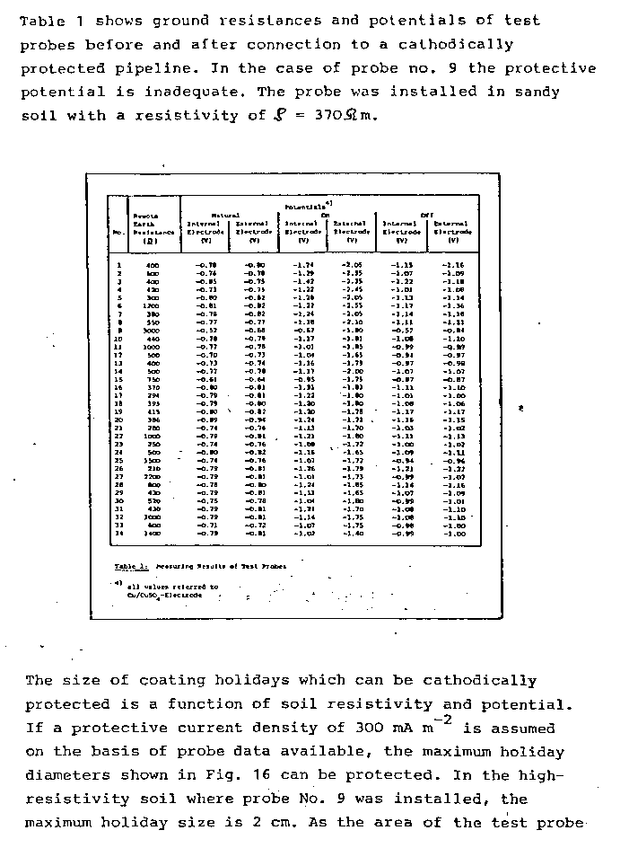
This is proof of the value of the Alexander Cell
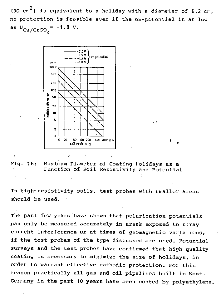
This paper is an acknowledgement that all monitoring used by other companies world wide is seriously questionable. CPN Technology has resolved all of the problems described above and can prove it by demonstration and computerisation.

Practical bench work to confirm this paper.
Field trip to confirm theoretical and benchwork integrity requiring a report.
On-line real time discussion.