
|
Cathodic Protection Training Course
Module 3
The importance of the reference potential.
|
|
A voltmeter can only display the difference between two potentials.
We are only capable of measuring voltages and they are NOT potential but are the differences between two potentials.
Both values must be known to calculate the difference.
In cathodic protection monitoring work we do not know either potential.
We are trying to measure the difference between two variable potentials
The result is that the readings on the meter or oscilloscope are meaningless but not entirely useless.
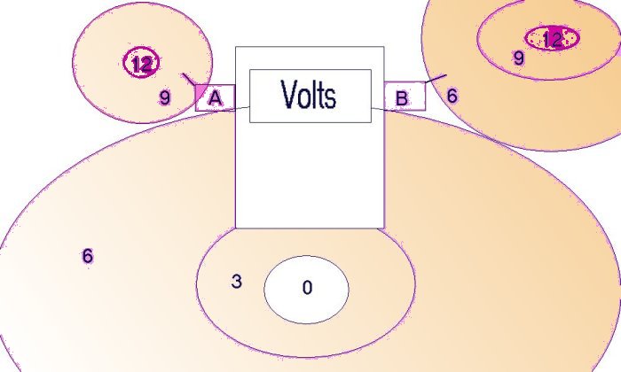
To display a voltage of 3 the meter must assign the value of zero to one pole of the meter that we shall call 'A' and measure the potential difference between that value and the value which is connected to the other pole of the meter that we shall call 'B'.
In the picture above we see that A is connected to an area that is electrically charged to the value of 9 and that B is connected to an area that is charged to the value of 6.
The meter will show a value of 3 as that is the potential difference between its poles.
The reason that the meter displays this value is that it assigns the value of zero to B. It is possible that everyone using a meter knows this but THEY DO NOT THINK ABOUT IT!
We see that the meter can display the value as negative if it has been programmed to assign the value of zero to A.
The experiments you have seen in Modules 1 and 2 of the Cathodic Protection Network on line course will allow you to understand that there is no such thing as a zero potential in real life. Indeed 'Gibbs Free Energy theory states in scientific notation that this is an impossible state and any vacant space will be automatically filled by surrounding energy. It's a bit like gas filling every avalable space and equalising the pressure within it's confines...... like in a balloon.
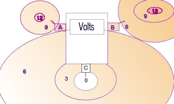
If we need to know the relationship between three potentials using a single voltmeter, we must take two readings. A-B=3 and A-C=9
or we can take the readings A-B=3 and B-C=6 in which case the meter has assigned the value of zero first to A and then to B.
It is clearly better that we relate both readings to one zero as this avoids calculations and confusion.
This becomes more obvious if we need to know the relationship between four potentials using a single voltmeter. We need only to take three readings providing we establish our own reference potential.
A=0 therefore A+B+-3, A+C=-9 and A+D=3.
Being able to think this way is essential to the cathodic protection field engineer and technician. It is the only way to visualize what is actually going on with regard to corrosion and CP currents.
It is possible to calculate the relationships of all potentials if we take different readings but it is unnecessary and confusing... so let's not do it.
Unfortunately, traditional cathodic protection readings do not have a common zero but it is possible to establish the common zero using standard Cathodic Protection Network Procedures.http://www.pipeline-corrosion-control.com/ProcHTML/proc.htm
There is a need for an international zero potential at a fixed location and I have been asked to present this need as a scientific paper at an international corrosion conference.
European Corrosion Conference
All corrosion science is based on understanding of the electro-chemical reaction that disolves metal and the thermodynamic models that explain the basic physics in which the natural laws are defined.
These basic laws are not opinions or debatable. They are codified on evidence obtained by repeated observation that can be witnessed and recorded by experiments or real life occurances.
The situation at present is that the known laws of physics cannot be used diagnostically in cathodic protection as we are not gathering data in a finite manner.
I have spent many years demonstrating this fact to the cathodic protection community globally.
Cathodic protection is extremely cost effective and is required by law in most countries of the world. Cathodic protection specialists have established themselves into powerful consulting positions and are trusted by friends in academic circles as well as operating companies.
The scientific and engineering communities however are less sure that cathodic protection is a science but refer to it as something of a mystery or even a 'black art'.
Further down the social scale it is commonly refered to as bullshit and a knowing smile says that it makes money so who cares?
When pipelines fail due to corrosion there is often loss of life, loss of product, disruption to energy supplies and environmental damage followed by massive legal expense and damages on a national scale.
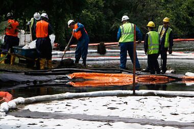
During this process those responsible for corrosion control come up with complex excuses for the failure of their advice expressed in a way that confuses the scrutineer and the public who quickly give up and address matters that are more easily understood.

It is for this and many other reasons that I set out on the course of action that has led to this paper.
Cathodic protection is the electrical control of the corrosion reaction and it is therefore necessary to demonstrate this reaction in a way that can be observed and measured in less than four hours, so that delegates can see for themselves that we are in compliance with the demands of scientific practice.
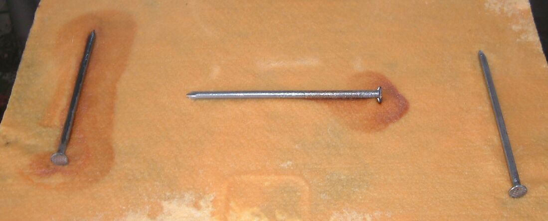
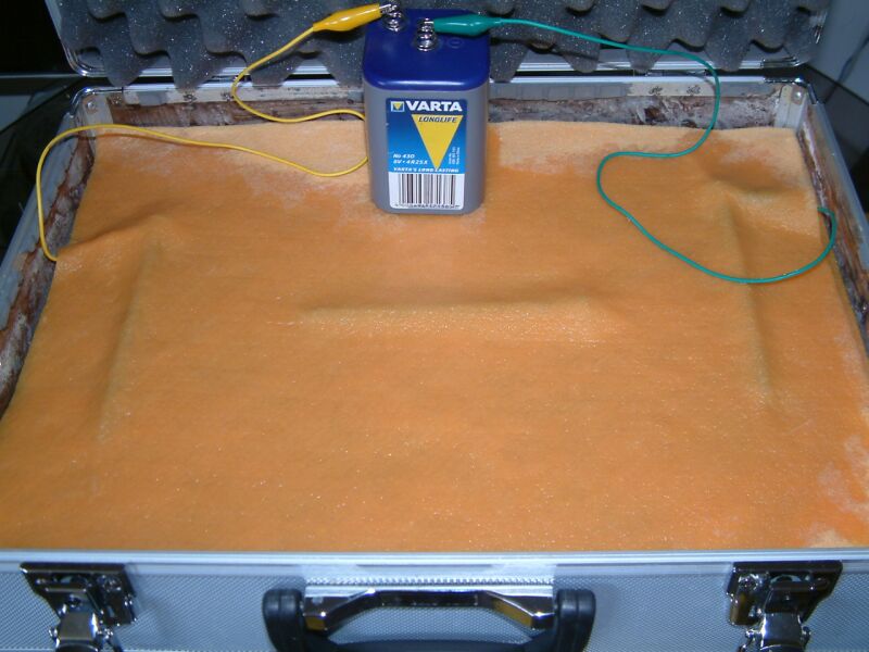
Demonstration 1 shows 3 bright new nails between layers of damp cloth connected to a dry cell battery that might be described as multiple corrosion cells in series.
The charges at the positive pole of the battery equalise with the charges in the first nail that then becomes the anode of this corrosion circuit.

The damp cloth will become charged in this area in relation to the cloth surrounding the far nail that is connected to the negative pole of the dry cell battery.
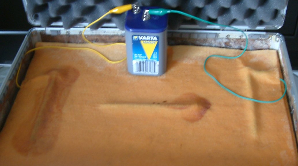
Electrical potentials equalise out as demanded by the laws of physics and this flow of charges is called current and measured in amps.
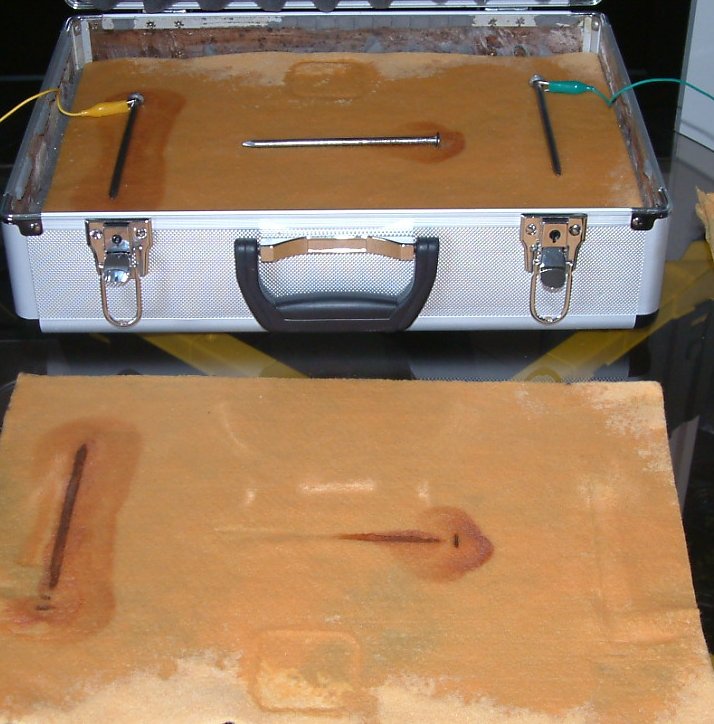
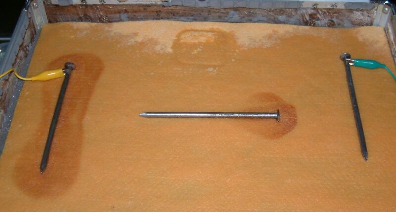
The nail in the middle is a low resistance path for the charges to take and the point of entry to this nail becomes it's cathode and does not corrode. The whole of the center nail becomes charged to a single potential resulting in the end closest to the third nail having more charges than the cloth in which it is embedded. The charges pass into the cloth at this end and this area can be seen to corrode as it has become the anode on this centre nail.
It is very important that delegates know that this demonstration can repeatedly show that the basic laws of physics and electro chemistry are presently being missunderstood by most practitioners of cathodic protection.
Using a digital voltmeter bought at any retail stockist in any country in the world it is possible to make measurements to confirm everything stated about demonstration 1. The probes supplied with the meter can be put in contact with the battery, the nails and the cloth at any chosen point and I invite delegates to try this for themselves.
We are dealing with an electrical circuit in which the source of charge exchange can be the corrosion reaction itself that we wish to control.
This source, and the charges it generates, are part of a greater circuit represented by metalic conductors such as pipelines and structures that are embedded in the ground and that in itself is the electrolyte of many other corrosion reactions.
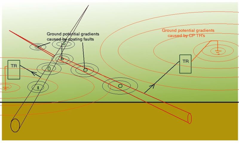
We therefore have no option but to address the complexity of electronic corrosion control from a global viewpoint.
A single pipeline cannot be isolated from other pipelines in that area as no coating can be perfectly applied and maintained. Railways and other structures are conductors in the area through which the pipeline passes and charges will equalise throughout the conductive paths according to the laws of physics applied by electricians globally.
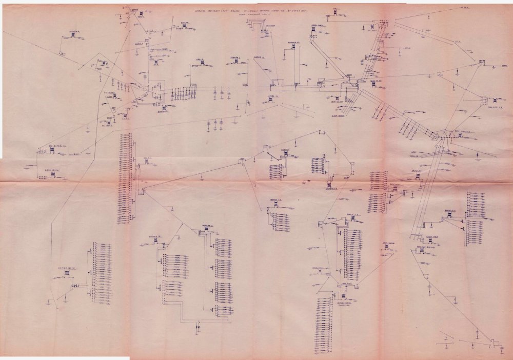
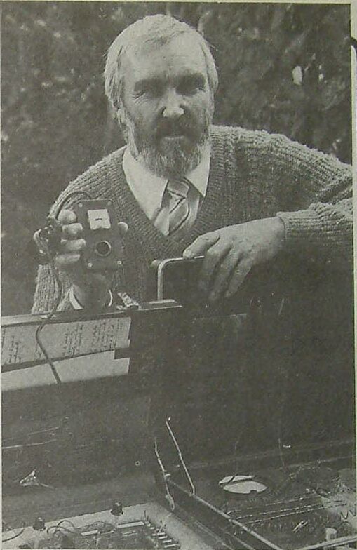
In the 1980's I built a physical model of a pipeline cathodic protection system in order to experiment with theories that I was studying at that time. A similar model is on display as part of this presentation.
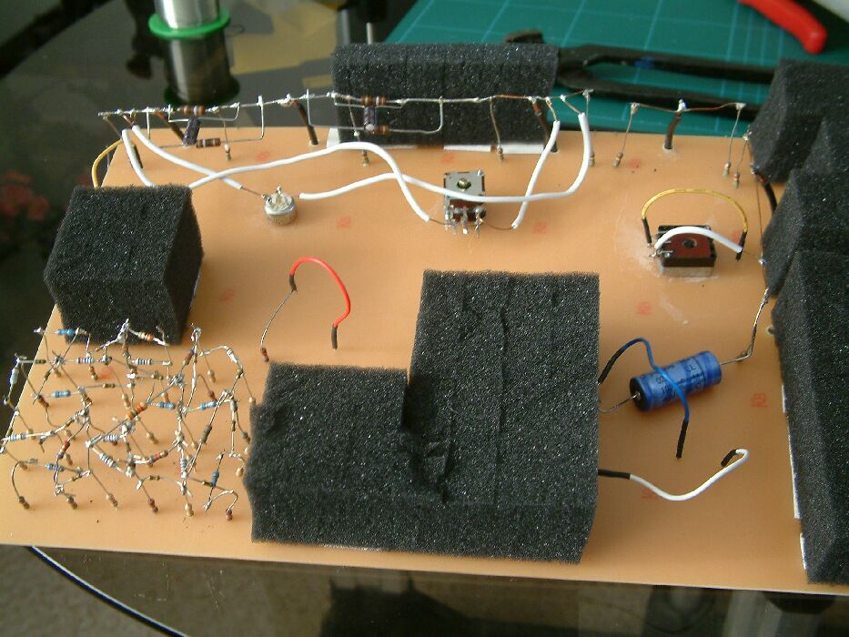
I was also able to model features of measurable cathodic protection on computer and these are also available to delegates of this conference.
This establishes a common reference for the whole of this particular pipeline area by relating each electrode to each other electrode.
This is a model of a coorsion cell subject to three different methods of measurement to obtain data.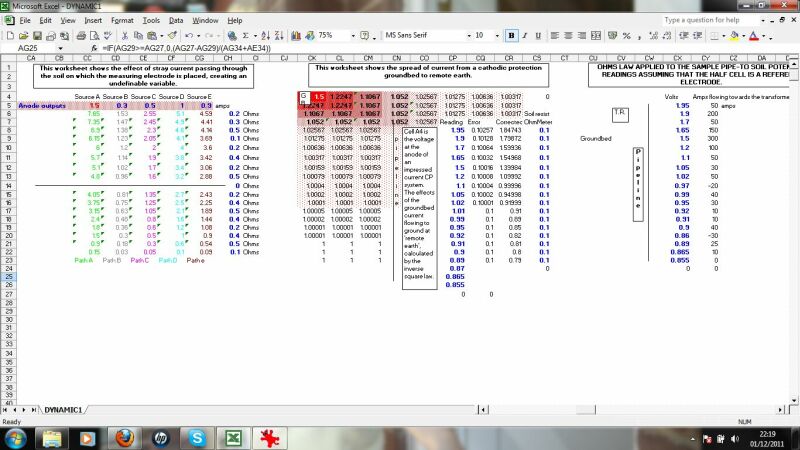
This section calculates the effects of stray currents, the distribution of charges from an impressed current anode and the effects of ohms law on the distribution of charges resulting from the resistance of the pipline metal itself.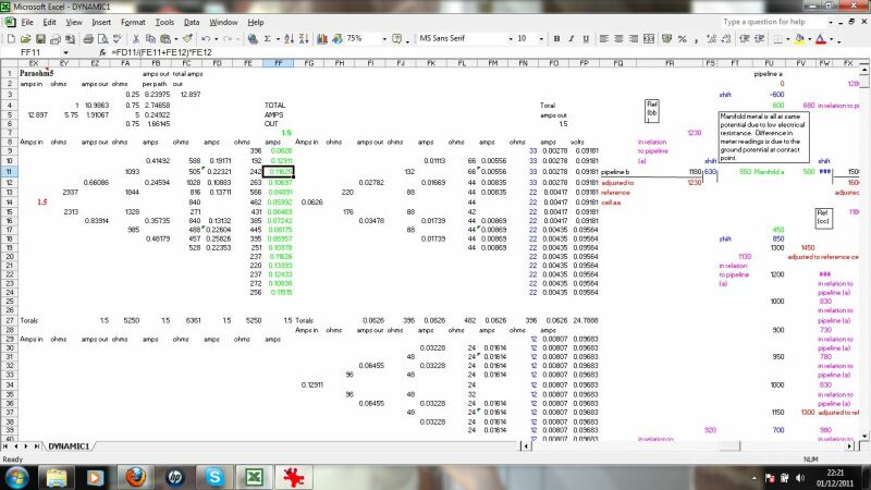
This calculates the charges dispersing from the impressed current anode to remote earth and the effect of ground resistance to their ingress at a coating fault.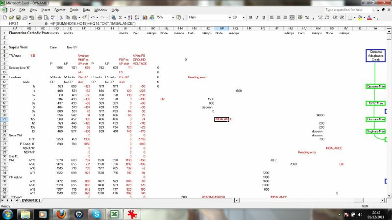
this checks the validity of data passing through the system by applying Ohms law and Kirchoffs laws at nodes in the circuit.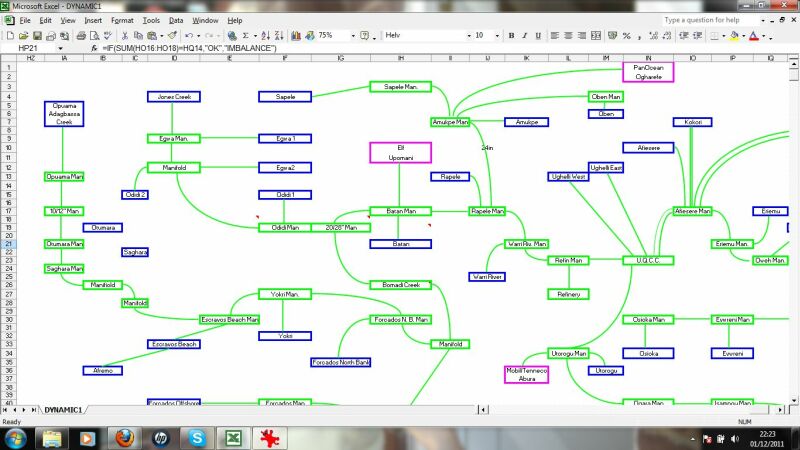
This displays the results schematically for an overview.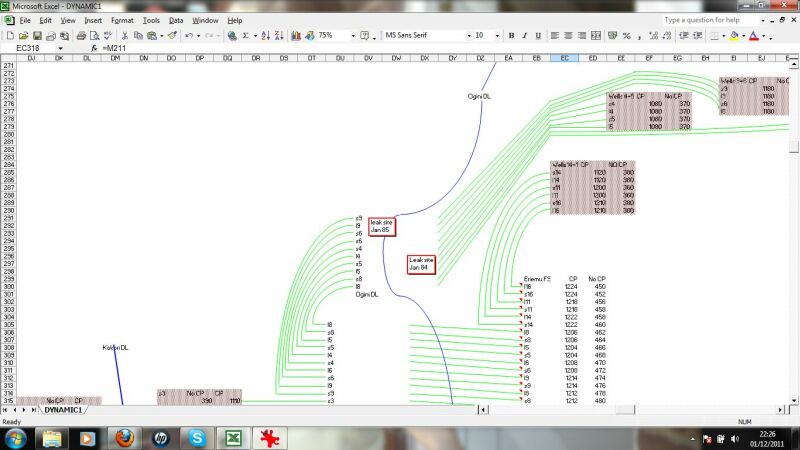
This zooms in to a schematic of a particular pipeline area, in this case wells and flowlines to a manifold.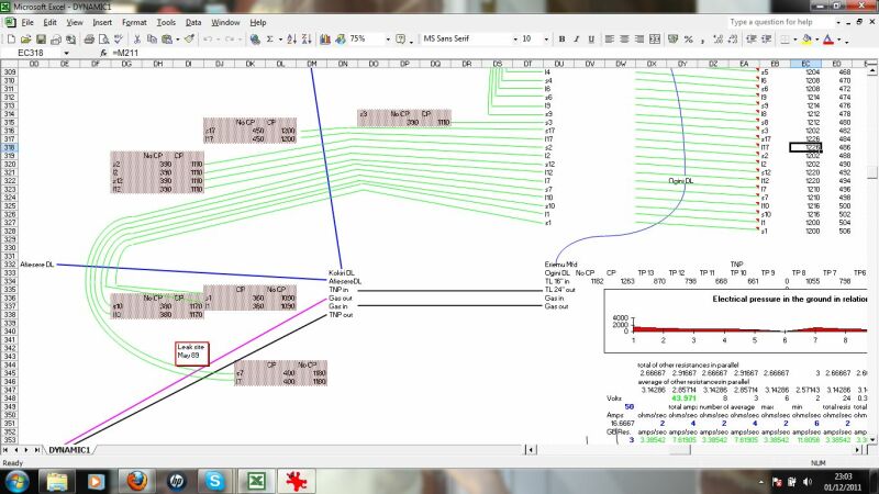
This display a combination of the calculations relating to the distribution of charges and direction of currents resulting from the cathodic protection systems and interference.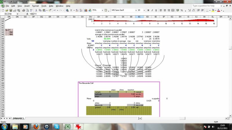
this shows the formulae and calculations from individual corrosion cells as affected by the overall electrical flux from properly gathered data and information.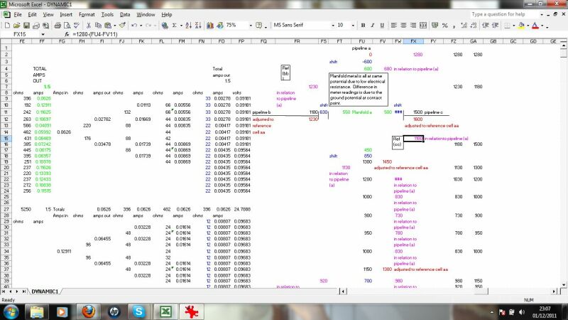
This calculates the equilibrium between the corrosion reaction EMF and the potential available in the ground along the pipeline.
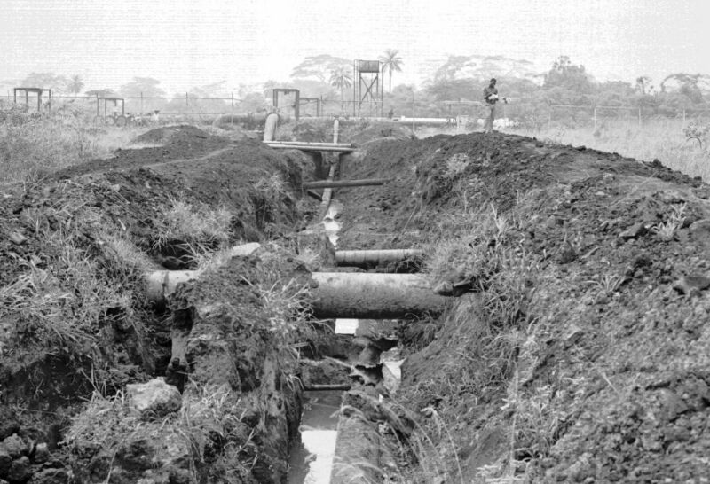
These studies, when practiced in field conditions, prove that the whole of Nigeria is one integrated circuit and that adjustment of a single cathodic protection transformer rectifier alters the equilibrium between metal and electrolyte throughout Nigeria.
I have no reason to believe that man made borders restrict the rule of natural laws when pipelines, railways and other conductive paths reach equilibrium in other territories.
Case studies have shown that 'interference currents' cause accelerated corrosion and also cathodically protect unintended parts of 'foreign' metalic structures.
Understanding interference can be achieved by circuit analysis and that is an essential part of the modern electronics industry.
Circuit design and control demand that there is an agreed zero potential on which we can base our rational and mathmatics.
I have proposed the need for a common zero for the purposes of cathodic protection design, commissioning and control in Brazil, Iran, South Africa and the UK as well as many other countries.
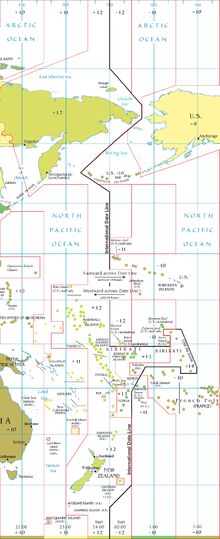
The proposal is that this paper establishes a single potential in the ground that can be used in the same way that GMT is conventianally used in relation to matters of the passage of time.

At present the common potential that is used for reference purposes can only be used in closed circuit conditions. The traditional usage of the Cu/CuSO4 electrode is attempting to measure a voltage in a measuring circuit tha includes mutiple variable potentials that cannot be individually evaluated.
The software that I have developed can relate each potential to each other potential measured correctly in the same area. In order to evaluate the interference between all systems we need to inclde data and information from neighbouring systems and to do this we need a convention similar to that established by the railway systems in the UK and the sailors of the world in relation to the international time line.
This work is requiring the co-operation of international organisations and multinational companies.
Cathodic Protection Network is a trust with intellectual property assets that are 'open source' to allow free exchange and growth of ideas and this IP is covered by common law covenent in perpetutuity.
In order to promote the spread of this science CPN administers the commercial aspects of this IP through a registered international company.
All interested parties are allowed to develop their own commercial activities but any claim to scientific validity using CPN IP will only be validated upon proof that the practice can be repeatedly demonstrated by case study with true data and pictures or personal competance will only be certified by personal demonstration of competance, knowledge and understanding.
This is not rocket science so we will not miss the target because one member is using yards instead of meters and this is not motivated by the ultimate competition of warfare.
I believe that this conference is about the preservation of the work of humankind and the protection of life, the environment and assets achieved by the efforts of many people accross all borders.
Back to Module03 index page