Cathodic Protection Training Course
Module 3
Open circuit measurements
This is a name used by Peabody of NACE to describe an electrical measurement made when one pole of the meter is connected to the electrolyte rather than a definitive point on a metalic circuit.
A normal electrical measurment is made by contacting metal conductors Such measurements can be studied in the confines of a laborarory or on a bench, using trays and containers with sufficient space to allow the movement of the contact point within the electrolyte.
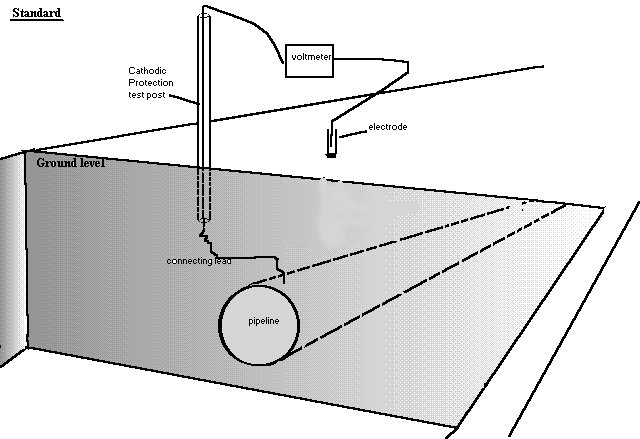
It will be seen that the measuring circuit of the standard cathodic protection measurement consists of a conductor from the negative pole of the meter to a conductor in a pipeline test post that is directly connected to the pipeline metal. The pipeline metal is then in contact with the ground/water at undefined coating faults.
The positive pole of the meter is connected to a conductor to a copper rod in a saturated solution of copper-sulphate. The solution soaks through a porous plug and makes contact with the ground/water.
It is realised that a silver/silver chloride electrode is traditionally used in sea water measurements but this does no make any difference to the measuring principles.
There is a volume of electrolyte between the pipeline metal and the point where the electrode contacts the mass of the electrolyte.
This electrolyte is conductive and can be perceived as a number of resistances in parallel.
The point at which the current to be measured passes through a deminishing number of resistances from the mass of the electrolyte to the point of contact of the electrode is recognised as 'shells of resistance'.
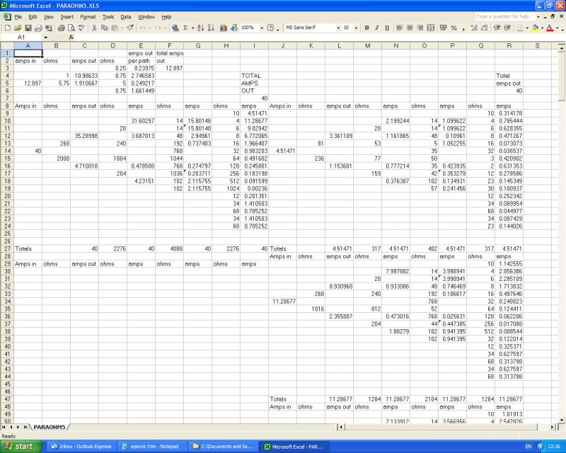
The effect of these shells of resistance can be measured using a galvanometer and a digintal meter as shown in the drawing below.
This can be carried out in the field or on a bench in a tray of wet sand.
It can also be replicated on a mathmatical model using a computer.
Each feature of open circuit measurements can be described mathmatically and tested on bench models and in the field.
It is obvious that these studies involve Ohms Law and that this can be used to determin the resistances in the immediate area of the corrosion reaction and the cathodic protection current paths.
The electrolytic path.
Attempts are often made to ascertain the resistance of the earth along the path of the pipeline. There are several methods used but all miss the point that the 'average resistance' of the wayleave is corrupted by the presence of coating faults.
It is necessary to study this as an electrical problem rather than an electro-chemical problem.
One difficulty is that the unit of measurement is ohm-meters or ohm-centimeters. this is NOT Ohms per centimeter or Ohms per meter!
This is not a value that you can say the further the distance the greater the resistance!
The reason for this is that the quality of resistance is subject to the laws of resistances in parallel.
The 'charges' radiate out from a point to an area where there are an infinite number of resistances in parallel... and therefore there is an infinitely low resistance.
click to return to Module03 index page