History of development of
the Cathodic Protection Network
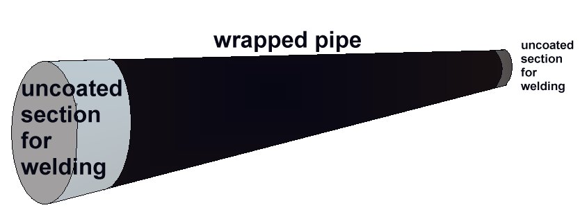
Pipelines are mainly made of steel and coated with material that protects them from chemical reaction with their backfill. This coating must be electrically resistant and is inspected immediately before the pipeline is buried or submerged.
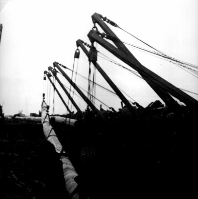
Steel pipes leave the factory in lengths of about 40 feet which are welded together into continuous lengths before lowering into the ditch. Each length has been factory coated but the gaps left for welding are coated in the field.
The coating inspection is known as 'holiday detection' from the old expression of paint inspectors that the painter had taken a holiday when leaving a bare patch. The primary inspection is visual plus a continuous spring ring is wrapped round the pipe and rolled along using an insulated handle which connects the spring to a very high voltage coil.
The voltage is set so that an arc occurs at a coating defect and rings a bell in the detector box. The inspector marks the fault which is repaired and re-checked.
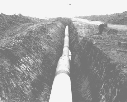
The detection and repair of coating faults delays the work of pipe laying which involves using heavy plant and equipment in difficult circumstances, all of which make it very easy to damage the coating further.
It is not surprising that coating faults are common.
The back-fill operation is inspected but often includes metalic and hard objects that can effect the cathodic protection measurements and physical condition of the pipeline when covered.
Cathodic Protection
Cathodic protection test leads are connected to the pipeline metal at intervals varying from half kilometer to one mile, depending on the country and operators specification. Additional test points are provided at locations where the pipeline passes beneath roads, railways, canals and rivers.
The test leads are very well insulated because they are copper and would tend to form a 'bi-metalic coupling' reaction causing accelerated corrosion to the steel pipe.
The test leads are bought to the surface through a pipe or concrete post set in the ground. The ends are normally attached to brass nuts and bolts which protrude giving access for electrical connection to instruments.
Vandals often damage these test posts so it is sometimes necessary to simply use a steel post and set the lead in concrete or epoxy compound to the top of the post.
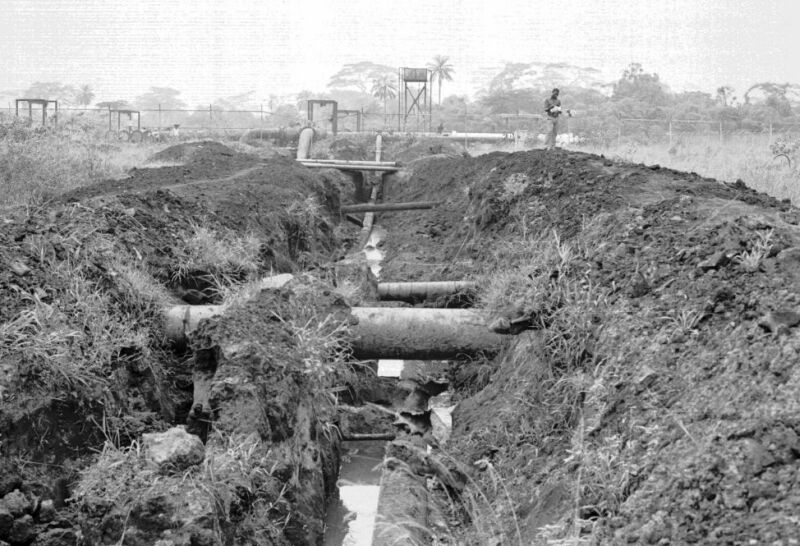
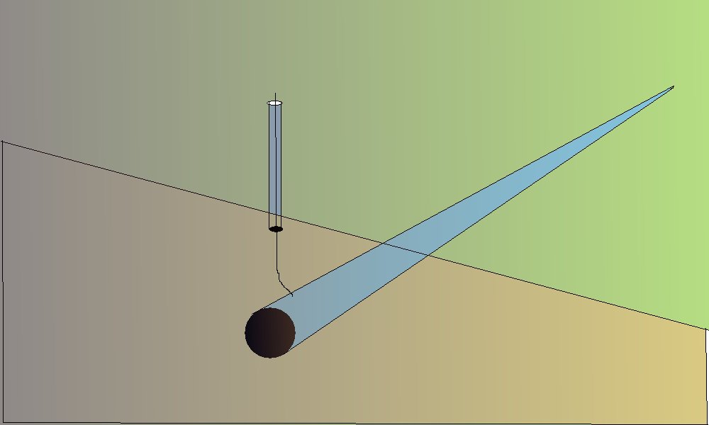
Cathodic protection Inspectors were required to connect the test lead to the negative terminal of a voltmeter, connect the positive terminal to an electrode described as a 'half-cell' which was placed on the ground directly above the pipeline.
It was thought that the half-cell was a reference potential against which it was possible to measure the voltage which would give an indication of the corrosion status of the pipeline metal.
Field workers found that moving the half-cell would produce a significantly different result and when they reported this the data was altered to suit the expectations of the clients consultant engineers.
From the 1950's to the 1970's, the source of scientific excellence and engineering guidance was a publication known as 'Peabodies' published by the National Association Of Corrosion Engineers.
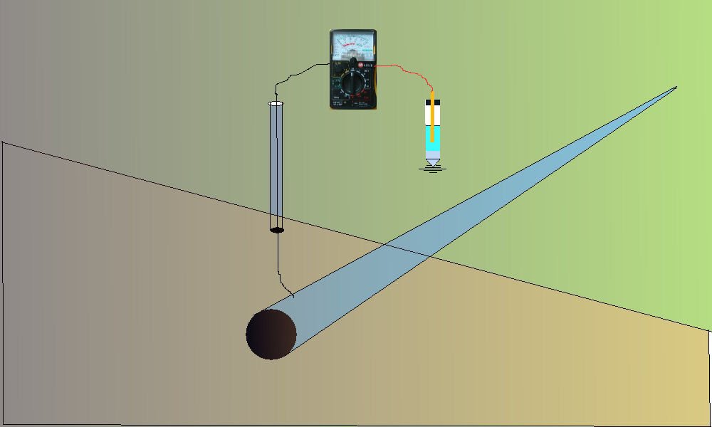
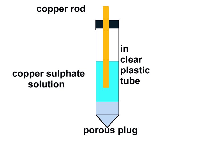
Scientists believed that the works of Pourbaix substantiated the use of a standard voltage -0.850v when measured between the pipeline metal and a copper/copper sulphate electrode as the criterion for achievement of cathodic protection.
Although cathodic protection had been a very cost effective success there continued to be disastrous corrosion related pipeline failures world wide and in the mid 1970's the method of making the field measurements was closely examined.
In 1974 I was appointed to the position of Corrosion Engineer for the Eastern Division of Shell-BP Development Corporation of Nigeria.
It was very clear that corrosion control was not effective as leaks were increasing alarmingly.
I was allowed to utilise some of my unique survey procedures to build an overview of the corrosion status of the region.
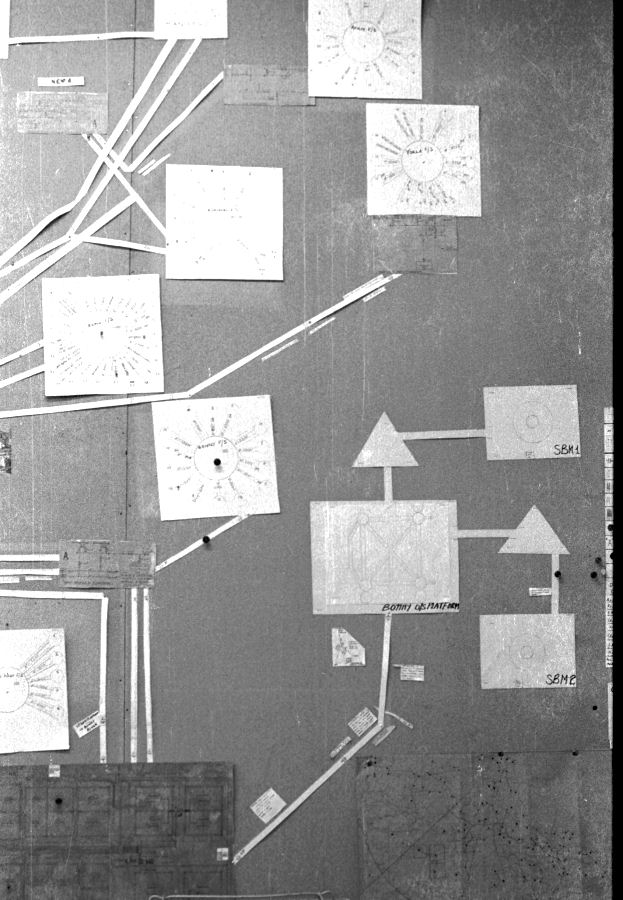
I specified the 'two half-cell' survey to a contractor Mark Derefaka in early 1975 at Bomu Manifold which had been bombed during the Biafran war.
Another manifold had been quickly built over the old one, to get the oil flowing, but there were no drawings of the old buried pipework as they had been lost in the destruction of some of the head office buildings.
This contract proved the value of mapping the potential profile of the ground and showed the exact position of all the old pipework prior to exacavation.
By regarding the whole network of pipelines as a massive electronic circuit, I was able to draw an equivalent circuit with impressed current systems and sacrificial anodes.
Pocket calculators had just become available so I was able work out the likely locations of corrosion using electrical laws and reconciling each part of the system.
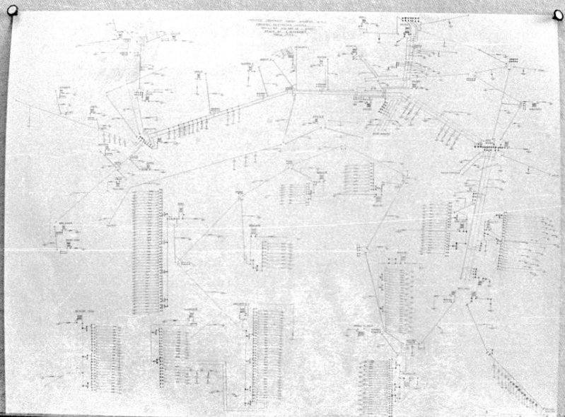
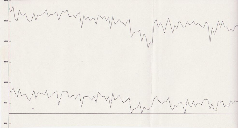
My survey teams would enter their readings on wall graphs using map pins linked with cotton.
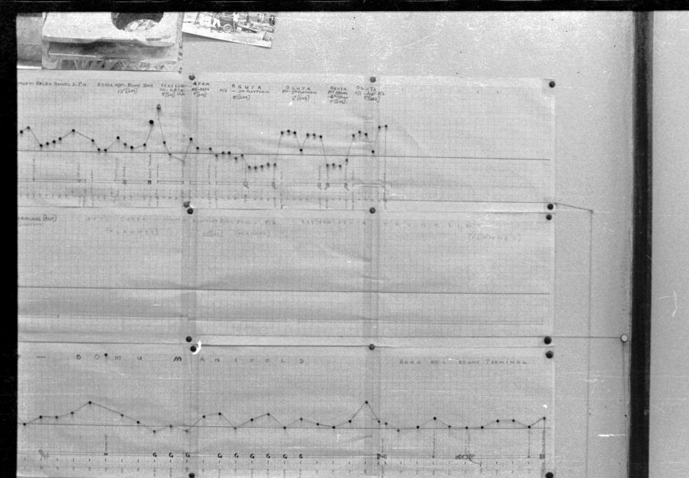
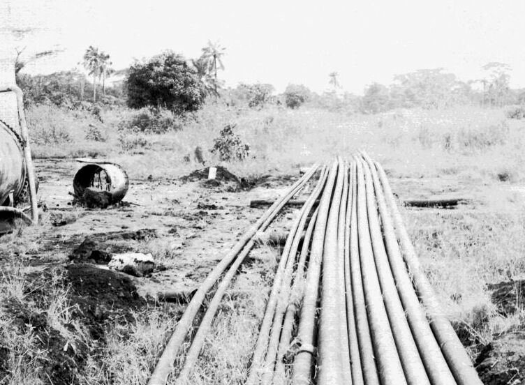
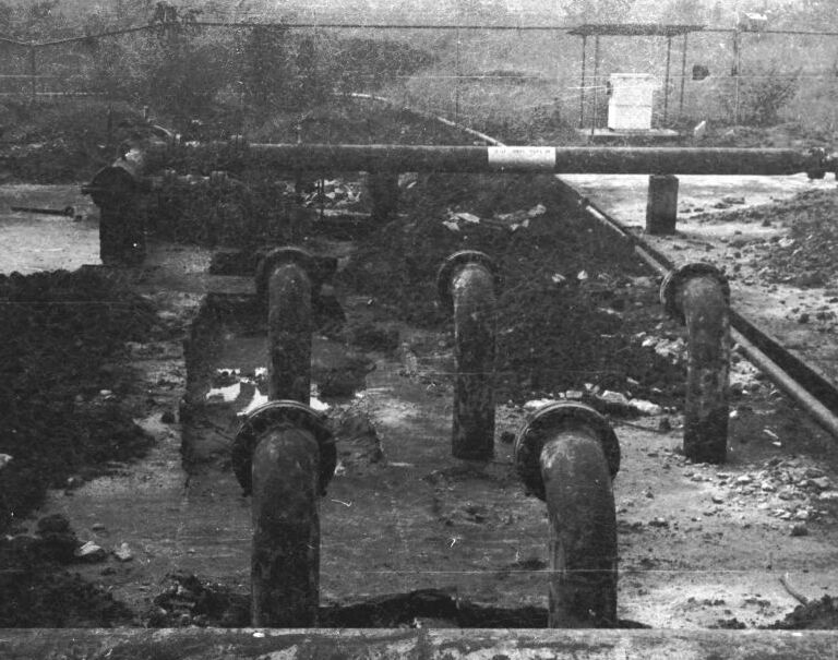
Direct Current readings were shown on cardboard strips on a wall mounted schematic of the pipeline layout of the whole region.
The picture above shows a very small section of the layout.
By comparing data from the files with present field data I was able to predict, with a fair degree of accuracy, the likely locations of corrosion failure in the immediate future.
On one occasion Steve Mayaki returned from an investigative survey having found that a predicted location had actually started to leak. This was immediately remedied with a leak clamp having lost only a few gallons of oil and virtually no environmental damage.
I was able to bring the whole corrosion crisis under control in a couple of years and reduce the incidence of external corrosion leaks to zero in four years.
This extensive period of investigation and prevention of corrosion confirmed that there is no way that the 'half-cell' can be used to establish a reference potential but that it is very useful as a probe to contact the electrolyte in which the pipeline or structure is burried or submerged.
If a bare metal contact is made then that metal reacts to the salts disolved in the electrolyte, thus adding yet another EMF to the measuring circuit.
In 1978 I realised that the only way forward was to try to devise a method of measuring the actual corrosion current and the effect of cathodic protection on the corrosion reaction itself.
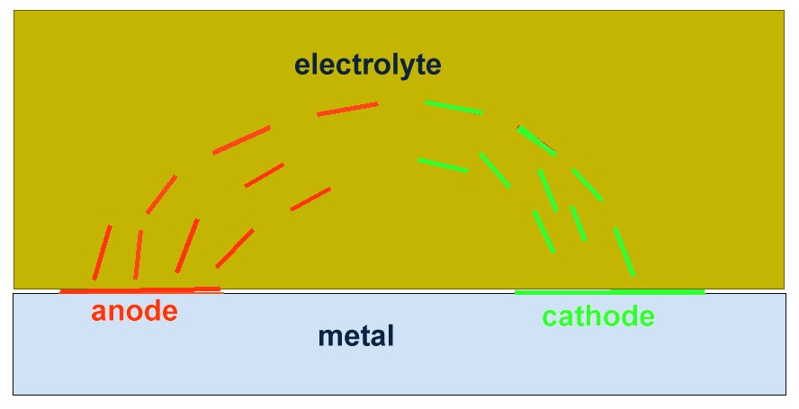
I used an assortment of metal coupons and sensitive meters but the problem was that the current must be measured without disturbing the reaction. The effect of the cathodic protection must be measured without disturbing the passage of that current onto either the anodic or cathodic interface.
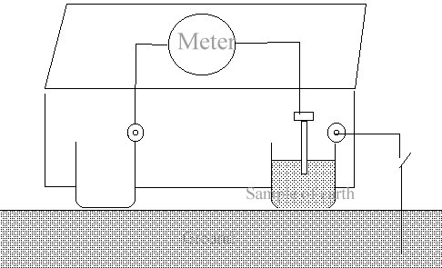
The only way to do this is to create a real corrosion cell in such a way that the corrosion current can be observed in any state of equilibrium.
Return to the UK
During a period of independant research and development in the UK I designed the Alexander Cell into a working unit.
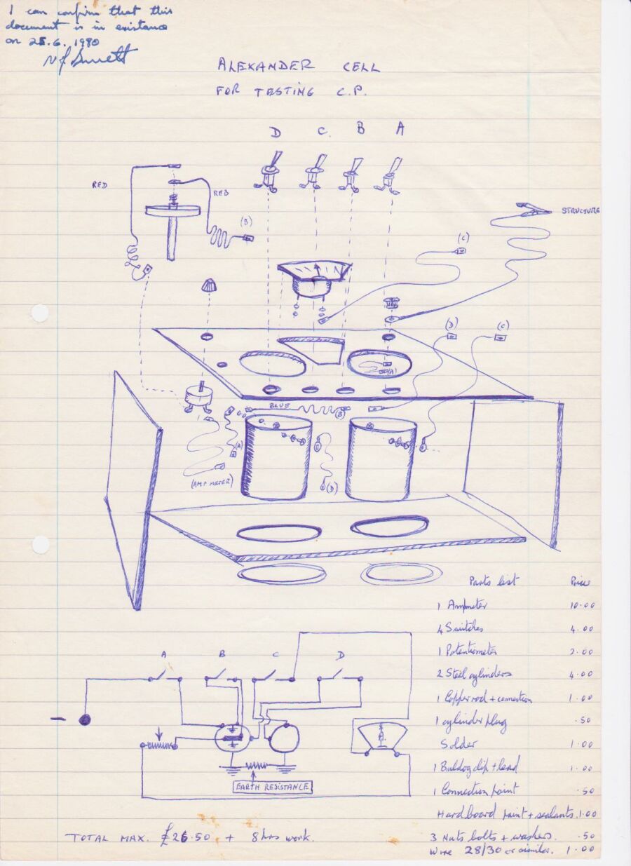
I had a solicitor witness the document above to substantiate that I had indeed invented and constructed the device myself at that time.
I then spent four years as a cathodic protection technician working first for Atkins Inspection and later with Global Cathodic Protection on contract to North Thames Gas.
Before I took the position I was interviewed by Mike Foskett, Chief Corrosion Engineer for North Thames Gas who was based at Staines. We discussed my experience in Nigeria and he agreed that I could conduct field trials of the Alexander Cell (in my own time) at North Thames Gas pipeline locations.
The project was to conduct a condition audit of many thousands of miles of high pressure gas pipelines delivering North Sea Gas to the north London area.
A mainframe computer had just been installed in Staines Head Office of North Thames Gas and the project was guided by Bob Greenwood of the Gas Council ERS.
The procedure being developed was known as OLI1 (Over Line Inspection) and was developed in stages to OLI4 which is now known internationally as CIPS (Close Interval Potential Survey)
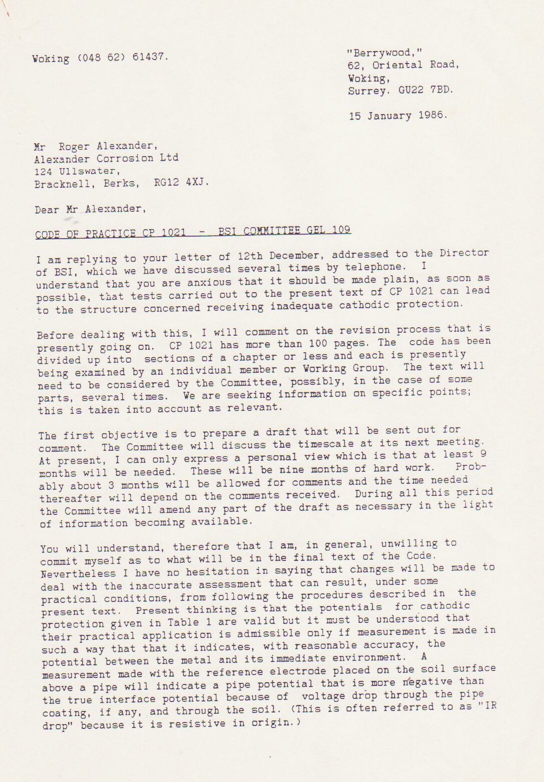
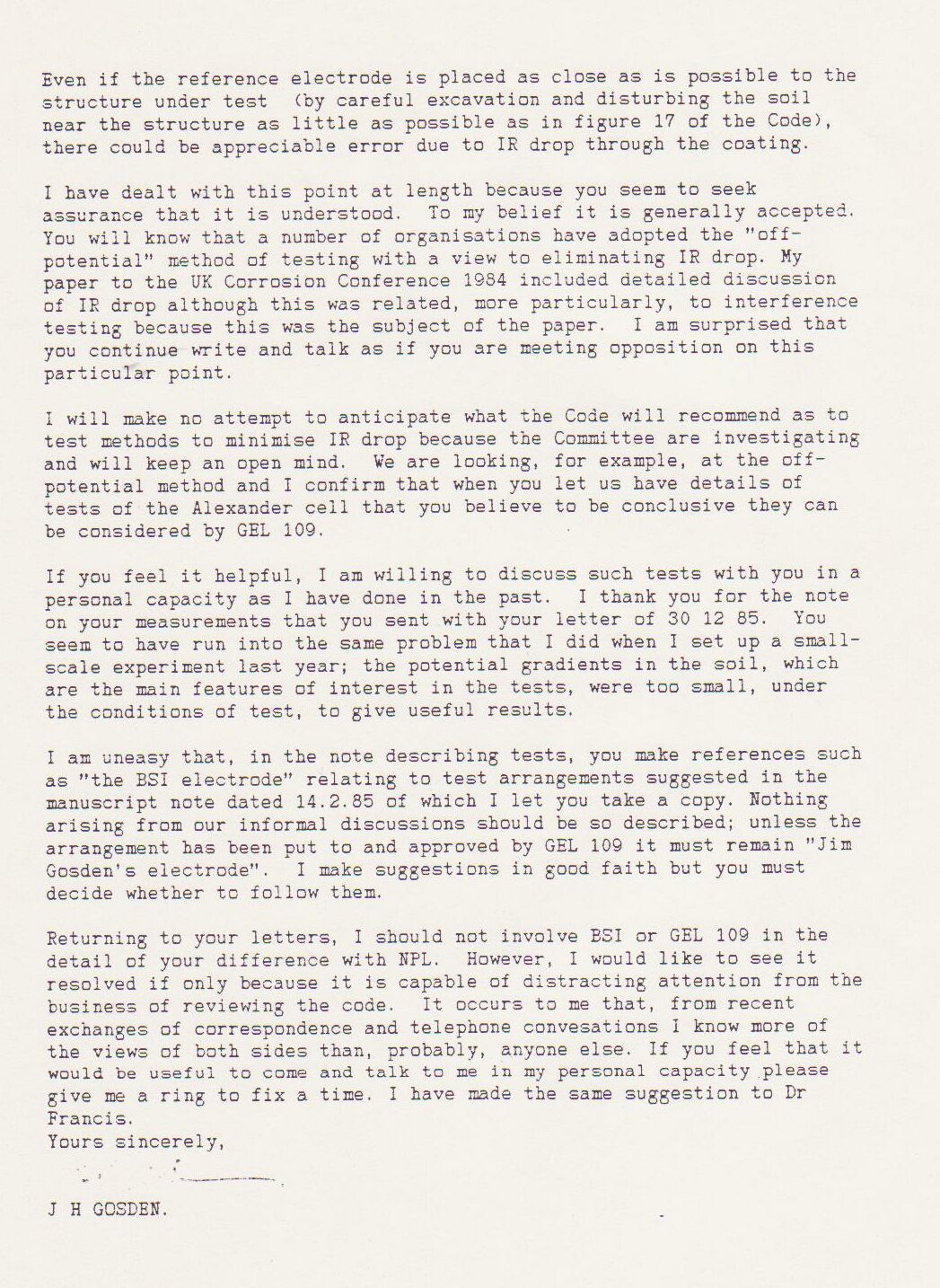
The reason for its development was the corrosion failures of pipelines that had been operated in compliance with the British Standards Institute Code Of Practice (CP1021) on which the pipeline licencing in the UK was based.
I joined one of four teams of technicians who were making notes of each voltage as the cathodic protection current was switched off and on at the nearest transformer rectifier.
Mike Fosket told me that they used the computer to plot the voltages in both states and that they had started by plotting the difference until they realised that this plot did not show the coating faults as they had hoped.
The theory had been that they could use the difference between the on and off readings to work out if the corrosion had been stopped.
In fact, they had found the principles that I had used several years before of plotting the ground potential profile.
I described the 'two half-cell' procedure that I used extensively in Nigeria and it was adopted as and additional check to locate the exact position of coating faults before excavation.
I was then required to carry out the final overline procedures, including the Alexander Cell, to produce a written report for each location before excavation.
The use of OLI4 procedures alone produced 7% accuracy and the complete Alexander Technology procedures produced 97% accuracy. The sampling was 100 excavations that I attended personally.
My success was such that Bob Greenwood visited site and saw the my procedures in action. He later authorised the purchase of an Alexander Cell, which prompted the Corrosion Engineer from South East Gas to buy one.
Mike Fosket asked me if I would like to write a paper about my view of cathodic protection which was radically different from mainsteam science at the time.
The paper was sent for technical editing to Dr Vic Ashworth of Ashton University, who rejected it completely with the comments that it did not fall within the concepts of known science.
Because of the success of my work in the field, Mike Foskette arranged for me to make a presentation to the London branch of the Institute of Corrosion Science and Technology.link to copy of the notes of that presentation
This was attended by over 100 qualified , practicing corrosion engineers 64 of whom signed the register.
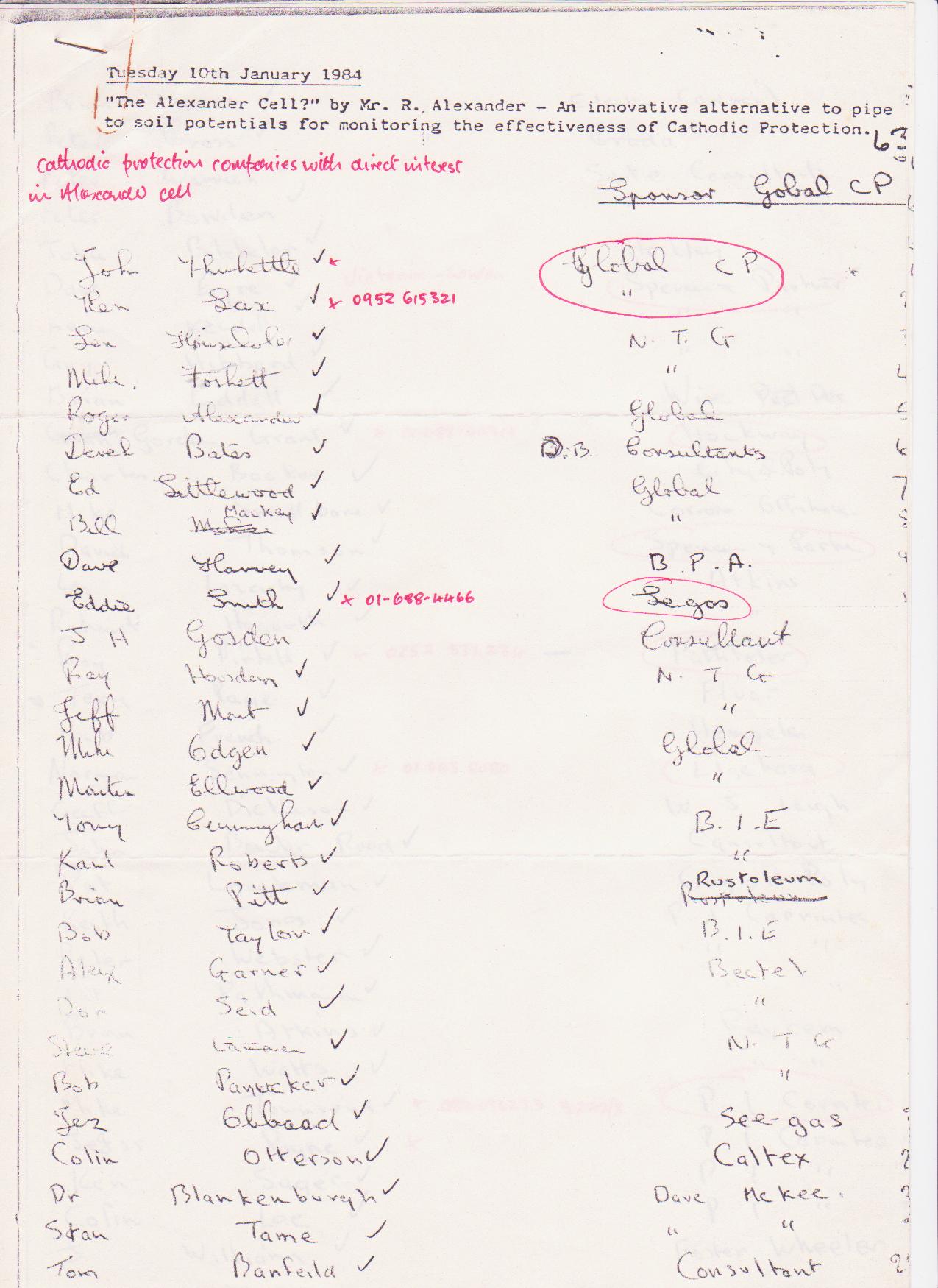
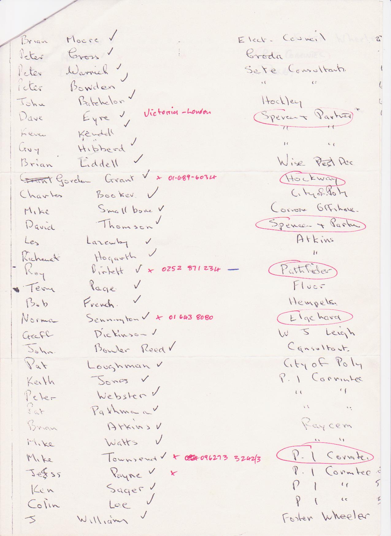
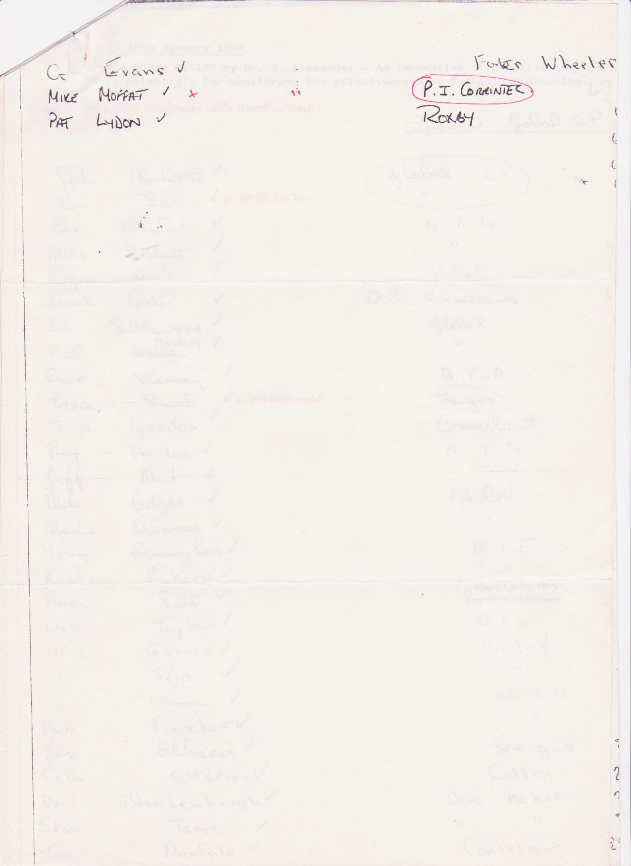
The presentation included demonstration models and videos of field work to support the content of the talk.
The Chairman of the BSI Committee for CP1021 attended and addressed the meeting after the presentation. He said that he supported everything he had heard and as a result was withdrawing the BSI Code of Practice 1021 for review.
John Tiratsoo published my paper in his journal Corrosion Prevention and Control and was then asked by readers to publish it in Pipes and Pipelines International, a journal that had 10 times the circulation.
I received positive response from all over the world and requests for the Alexander Cell.
Back to module02 index