
|
Cathodic Protection Training Course
Cathodic Protection Training Course
|
|
Module 1 page 2
VERY IMPORTANT.
A POTENTIAL can only be measured in a laboratory as the voltage that we measure must be compared to a standard potential (that is agreed by convention) and must be measured in closed circuit condition.
Therefore, the term 'pipe-to-soil potential' is incorrect and should not be used, as this will confuse those who know what a potential really is.
Therefore those who use the term 'pipe-to-soil potential' must either not understand or be deliberately intending to confuse.
Any document or scientific paper that includes the term 'pipe-to-soil potential', or any abreviation that means this, cannot be believed until the method of measurement is described in detail and the word voltage used instead of the word 'potential'.
I have gone into great details to explain electricity in a manner that allows you to make experiments to repeatedly observe the evidence.
A potential is an electrical quality and a voltage is a measurement between two potentials.
Everything has an electrical potential that we can measure by comparing it to another electrical potential with a meter.
A multimeter displays a voltage because it sets the zero at the energy level of the black terminal that we refer to as the negative pole of the meter.
An oscilloscope does not set a zero but can be adjusted to show the trace caused by the passage of electrons as they pass through the measuring circuit.
There can be no such thing as zero potential as that would be a void in the structure of the universe and scientists (Gibbs Free Energy.... look it up) have defined that as impossible.
A voltage is always relational and we must have a standard potential to relate every voltage to.
It is seen in the 3 nails experiment that the copper/copper-sulphate electrode cannot be used as the standard potential we need in cathodic protection field work.
In a closed measuring circuit conditions it is possible to relate the reaction of copper to a saturated solution of copper sulphate to the reaction of hydrogen to platignum as is shown in DIN50918.
DCVG proves that the measurement that we make in cathodic protection field work is between two ground contact electrodes that reflect the ground potential at the contact point.
This ground potential results from many electrical charges from an indefinable number of sources of energy.
When we switch one of these sources of enegy on and off we can mesure the effect of that switching but not define the corrosion status of the peipeline or metalic structure we are trying to audit.
What is cathodic protection?
Cathodic protection is an electrical way of stopping corrosion.
In order to understand cathodic protection it is crucial that an engineer can visualise 'electrical pressures'.
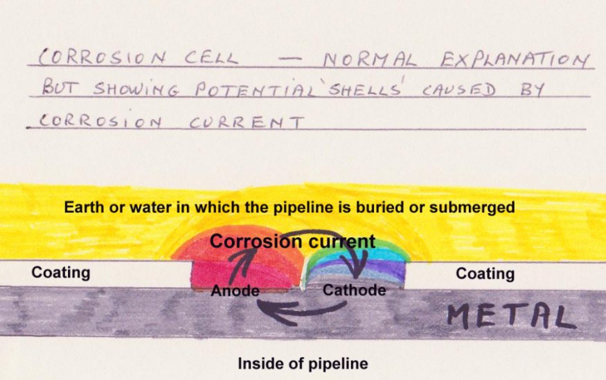
I drew this picture in 1980 to explain how I visualise a corrosion cell differently from the established teachings. 36 years later and the mainstream do not see the significance of this simple, crude drawing.
This is a typical illustration of a corrosion cell with the arrows showing the direction of the current.
This current is driven by the 'pressure' (Electro-Motive Force) of the corrosion reaction that is taking place on the surface of the metal.
Anyone who knows anything about making electrical measurements can see that it is impossible to measure the corrosion current in a corrosion cell on a pipeline because we cannot separate the anode from the cathode.
The picture also makes it clear why scientists use the term 'IR drop' and not voltage.
You will note that the CORROSION CURRENT is not linear, it radiates out of the anode and converges into the cathode. There are very complex formulae to describe the transfer of energy that we cannot apply in the field and are unnecessary to memorise.
During the passage of these charges they obey Kirchhoff's laws about electrical resistances in parrallel and follow the inverse square law of radiation.
Even in a laboratory it is impossible to calculate the effect of these circumstances on the measurement of the potential produced where the metal meets the electrolyte so a capillary must be used.
This comes back to the inderstanding of DIN50918 where you can see the capillary to the working electrode (anode) of the corrosion cell that is separated from the return electrode (cathode of this single corrosion cell).
The electrical pressure at the anode of this natural corrosion cell drives electrical current through the electrolyte to any location with a lower electrical. This increases the electrical pressure close to the cathode and causes the charges to re-enter the metal and complete this corrosion cell circuit.
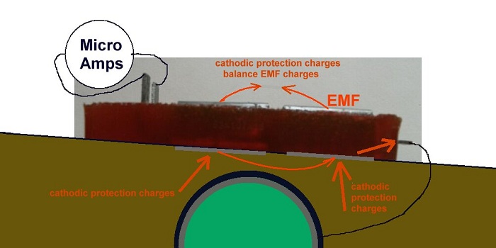
I designed the Alexander Cell to separate the anode from the cathode and to make it possible to subject this single corrosion cell to the electrical pressure in the electrolyte surrounding the pipeline or structure.
The difficulty was to see the effect of the cathodic protection current that passes to the pipeline through both the anode and the cathode of each corrosion cell.
This is described in detail later in the course where I show how to make an Alexander Cell.
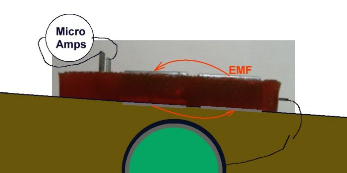
During the development of the Alexander Cell I experimented with bi-metalic couplings in the field and on the bench.
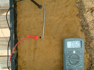
This next picture shows how we can measure the voltage between a piece of copper and a piece of steel when they are in earth.
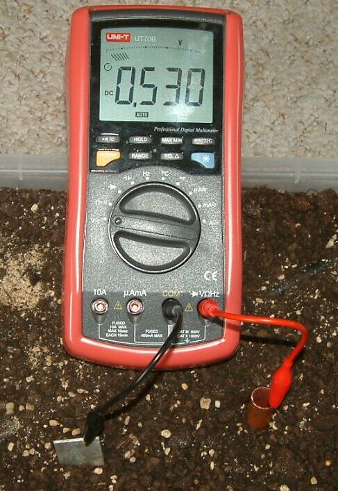
This meter is showing that there is a voltage of 0.530 between it's negative and positive poles.
An electrical pressure is known as a 'potential' -and this word must not be confused with a voltage. A voltage is the difference in potential between two points, measured in volts. It is a relative measurement and we all know the importance of relativity in science.
The relationship between voltage, current (measured by ammeters) and resistance (measured in ohms) is defined by Ohm's Law.
When measuring voltages any potential can be regarded as zero for the purpose of graphic display and calculations.
A potential is measured relative to another potential using a voltmeter so that the potential difference can be expressed in volts.
We do not have field instruments that can measure ions or pH values at the exact locations needed to apply the Pourbaix Diagrams so we have to rely on electrical measurements. (the base line of the Pourbaix diagram is pH). Cathodic protection technicians and engineers should imagine the 'electrical pressures' as we use the instruments to measure electrical values.
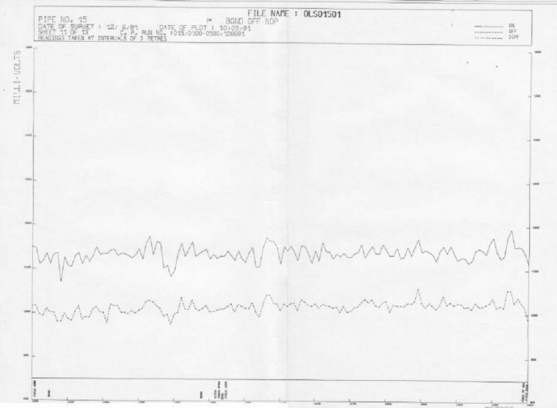
The graph above only shows the difference between the two potentials at each point of measurement. There is no reason to suppose that any two voltages are related because the baseline of the graph is variable relative to the readings. This is because the meter sets a zero for each measurement. This graph is simply a number of voltages joined together by a line that joins the dots. This fact is dealt with in depth during this course, including practical experiments.
This applies to all DCVG and CIPS graphs and reports. The voltmeter sets the zero for each measurment.
The above experiment will confirm that the graph base line is a 'floating zero'.
We must now watch corrosion in action by setting up the 3 nails experiment that I devised, filmed and uploaded.
During this experiment I set up a timer and an oscilloscope as shown in this short video.
After just over two hours you can see corrosion products that prove the metal going into solution as defined by Farraday.
All students should set up their own 3 nails experiment as it confirms many matters about cathodic protection.
This picture from the three nails experiment shows in two dimensions that corrosion current is NOT DIRECTIONAL but in fact it follows the paths of least resistance according to Kirchhoff's laws. It is important that cathodic protection specialists understand this and can imagine it. We can use our voltmeters during the three nails experiment to confirm to ourselves that this is what we will find in field work.
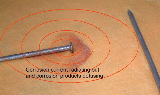
Corrosion produces 'electro-motive-force', which drives current into the electrolyte, causing the potential of the electrolyte to increase and the corrosion current to radiate out into the surrounding electrolyte.
Corrosion is a chemical reaction that discharges electricity from an anode to a cathode through the electrolyte. Metal is changed into rust at the anode and the metal at the cathode remains undamaged.
The current generated at a coating defect takes the least line of resistance to return to the pipeline metal
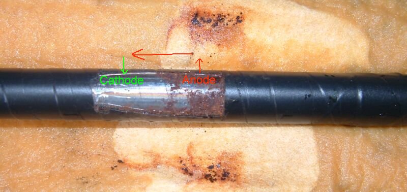
The point where current enters the metal is known as the cathode. No corrosion reaction is possible at this site as the potential of the electrolyte is greater than that of the metal at this immediate interface.
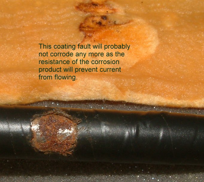
The reaction can continue until equilibrium is reached between the chemicals and the electrical energy. The chemicals have 'eaten away' all the metal and have run out of 'food'. No current is produced and so the whole coating fault is 'at rest'. Corrosion product builds up on the metal blocking the path of the current.
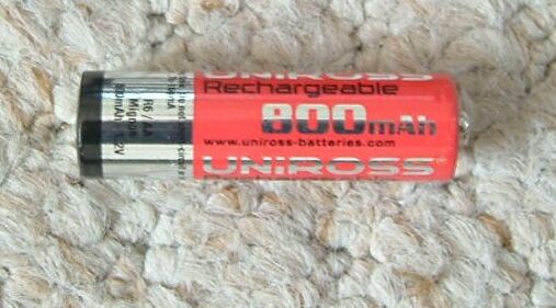
Batteries work on this principle. When batteries reach equilibrium we have to re- charge or discard them.
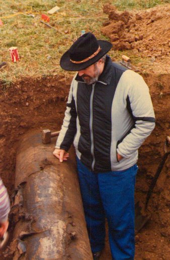
The public are not generally aware that our gas and oil comes to us through pipes that are inclined to rust but are protected by 'Cathodic Protection'.