
Cathodic Protection Study 4
INTERFERENCE CURRENTS IN AN OPEN CIRCUIT
MEASUREMENT.
OPEN CIRCUIT MEASUREMENT.
The measurement under discussion, has been described as an 'open circuit measurement',
presumably because one of the poles of the voltmeter is connected to a position in an
electrolyte where currents can flow in an open, or unrestricted direction.
Currents resulting from electrical sources outside of the cathodic protection circuits can effect
the meter reading in open circuit measuring. These are known as 'interference' or 'stray'
currents and only effect the corrosion rate where they pass onto or from the metal to the earth
(electrolyte).
Stray currents can effect the meter reading without necessarily interfering with the control of
corrosion.
LABORATORY WORK
When a reference electrode is used in the laboratory, very exact conditions are arranged so that
the measuring circuit is not subject to interference and contains no indefinable variables, but it
is not possible to make such an arrangement in cathodic protection field work.
CATHODIC PROTECTION FIELD WORK
Field measurements contain massive variations resulting from factors which have nothing to do
with corrosion of the pipeline. Stray current errors cannot be removed from the measurement
by switching off the cathodic protection current.
THE SPREAD SHEET MODEL
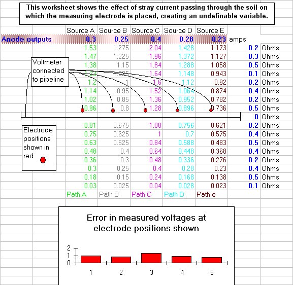
The spread sheet CPSTUDY4.XLS is a very simplistic model of the effect that stray currents
have on voltage readings measured between a pipeline and electrodes placed in positions that
are shown to be subject to a variety of 'foreign' currents.
The model assumes perfect coating, with no interaction between the pipeline and the stray
currents. (There are many such sections of pipelines where readings from stray currents give
unnecessary concern, as they can in no way effect the corrosion rate of the pipeline, from
which they are insulated.)
The model is extremely simplistic as it only allows the current from each anode to pass straight
to its own cathode. It is appreciated that, in field conditions, the currents would pass in a
hemispherical path through the electrolyte, and each would effect the potential of earth in all
the other paths.
The pipeline shown in the model could be a kilometre long and the connection is made to a
single test point, using a long trailing conductor to the meter which is then connected to the
electrode. The electrode is then placed in contact with the earth above the pipeline at equal
spacings along the kilometre of the pipeline route.
In order to simplify the model we imagine that the earth resistance is in straight line bands
running parallel to the pipeline on either side. The DC current passes through each of the
bands at right angles to the pipeline and the earth voltages along each current path are
calculated using Ohms Law.
USING THE MODEL
The model interference anode outputs and ground resistances can be altered to show the effect
on the ground potentials at the point of electrode earth contact. The degree of error caused
by 'stray currents' or 'interference' can be seen on the bar graph at the bottom of the sheet.
CONFIRMING THE INTEGRITY OF THE MODEL
This model can be tested in a field experiment by placing batteries and variable resistors, with
anodes and cathodes to earth, as shown in the model. Real life interference currents exhibit a
similar influence on cathodic protection readings but the sources and magnitude of the errors
caused are not easily definable.
Return to main page