Cathodic Protection Network Buried Pipeline Survey Kit
Abstract.
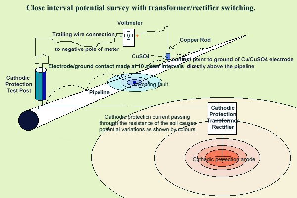
The two half-cell survey was devised in 1975 as a method of detecting location of coating faults on buried pipelines and structures. It achieves this by comparing the electrical potential of the ground on the surface above the pipeline. The Close Interval Potential Survey was devised in the 1980's as a method of assessing the corrosion condition of a pipeline.
The term 'close interval potential survey' was used to differentiate between the traditional surveys at test posts and the surveys where a trailing conductor allowed the pipeline potential to be compared to the potential of the ground immediately above it.
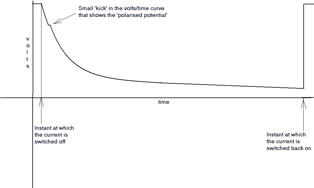
At the same time it was believed that a true 'polarised potential' could be measured immediately after the impressed current cathodic protection had been switched off. There is a scientific reason for this that has been misunderstood, resulting in a complex requirement for synchronised switching of transformer rectifiers that never works properly in the field.
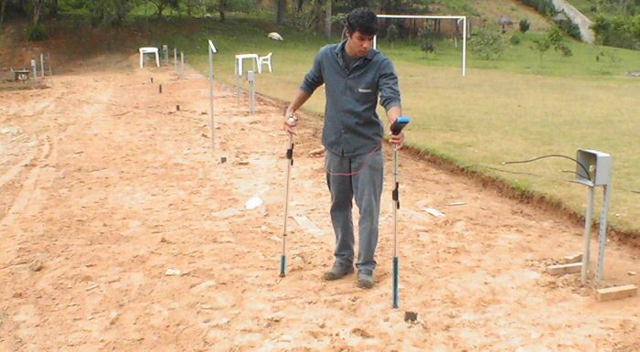
CIPS surveys are now carried out using two probes as walking sticks giving continuous contact with the ground potential that is compared to the potential of the whole pipeline metalic mass.
The voltages are displayed as point to point graphs that show trends from which we can analyse some aspects of the performance of the cathodic protection systems.
Available instrumentation and equipment is unreliable and cumbersome so CPN is going to supply an alternative kit.
Our first consideration is the person who carries out the surveys. He has to carry everything he requires over difficult terrain in the full range of weather conditions. Support vehicles might be many miles away during periods of the survey.
Suitable foot and leg wear must protect from snakes, be waterproof and tough. The soles of footwear should be electrically insulating to industrial standards to offer some protection against lightning strikes and contact with 'electric fences'.
Protective headwear must be light and comfortable and conform to industrial head protection standards. We will build in a digital camera and GPS aerial. It will be wide brimmed to shade from the sun and rain. The rim should be capable of being fitted with mosquito netting and the cavity on top of the head can house a small computer fan when required. The hat must look smart, be cool, fashionable and fit for purpose.
The walking sticks (sometimes refered to as canes) will be made of hollow tubes with screw on handles and detachable carbon fibre bush tips.
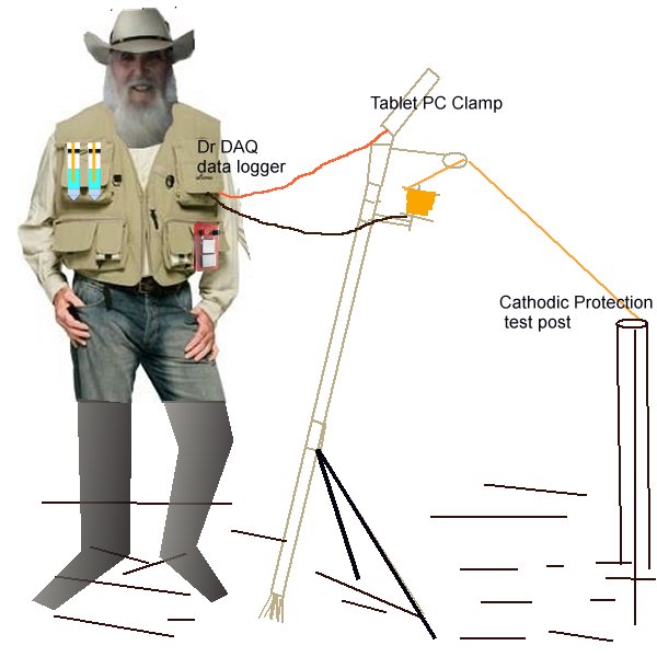
The handle will compose of a spool 'reel' arrangement (like the type of fishing reel where the line unwraps itself fron the top of the imobile bobbin) and a clamp to hold the tablet computer.
The bottom of each stick will have two spokes that will expand to form a tripod with so that the whole of each stick can be stood independantly on any type of ground.
The Back pack will accomodate food and drink, spare batteries and a first aid kit.
The waist coat will be as those available for fishermen with pockets everywhere.
The pockets will contain
1. A Dr DAQ data logger/osciloscope as the main instrument. 2. A pH probe. 3. A digital thermometer. 4. An Alexander Cell 5. Sealable sample bags. 6. A Champion Swiss army knife. 7. A Ledermann tool. 8. Sun shades and UV cream. 9. Notebook and pen. 10. A multimeter capable of data logging and micro amp measurements.
Method of survey.
We contact the ground with two 'walking sticks' that have electrically conductive tips.
These tips are connected to a data logger that records information and stores it in a format that can be transfered to a computer for analysis.
The instrument that we use at present straps round the neck of the surveyor with a harness that allows operation and observation of the measurements.
The main instrument is the data logger and we will use the Pico product called Dr DAQ in the first instance
The Dr DAQ will be placed in a waistcoat pocket and connected to the tablet computer with a USB connection. A spare connecting lead will be in the back pack.
The first thing we need is a means of carrying the gear cross country for great distances by an ordinary person on foot.
the data logger will fit into one waistcoat pocket and be connected by USB to the tablet computer mounted on top of one of the 'walking sticks'
The method of holding this has already been made in Brazil and South Africa
the ground contact tips are subject to non-disclosure at present as they may be patented... they are unique
The battery pack will consist of dry cells that are available at retail outlets all over the world.
The kit will include a digital thermometer, a pH probe and an Alexander Cell that will all fit in the waistcoat pockets
All probes will be connected by usb leads when needed
The survey necessitates that a long conductor is connected to the pipeline and this is done at the connection points that are provided during its construction.
We achieve this by mounting a 'fishing reel' type of gadget on top of the same walking stick as the tablet PC
This will allow the surveyor to connect from the Dr DAQ through the real to the pipeline test post
as he walks the wire will feed off the reel and keep the connection with the pipeline.
The GPS of the tablet PC will be connected to one input of the Drdaq data logger as necessary to synchronise location identity with time and data
The tablet PC will be used to make reports and take photographs that will be time stamped to synchronise within the CSV records stored by the tablet PC
Both walking sticks will be provided with folding tripod arrangements to allow them to be stood independently during specific survey procedures.
A conventional digital multimeter with data logginf capabilities will be carried in another pocket of the waistcoat. This must be connectable to the tablet computer.
The backpack will combine a small folding stool, a folding umbrella, some water and a lunch pack.
The kit will include a Swiss Army knife and a lederman folding tool
The spare pockets of the waistcoat will contain pencil, notepad, spare connectors and emery cloth to clean connecting wires.
sufficient spools of trailing wire will be carried by belt attachment for ease of replacement without taking the backpack off.
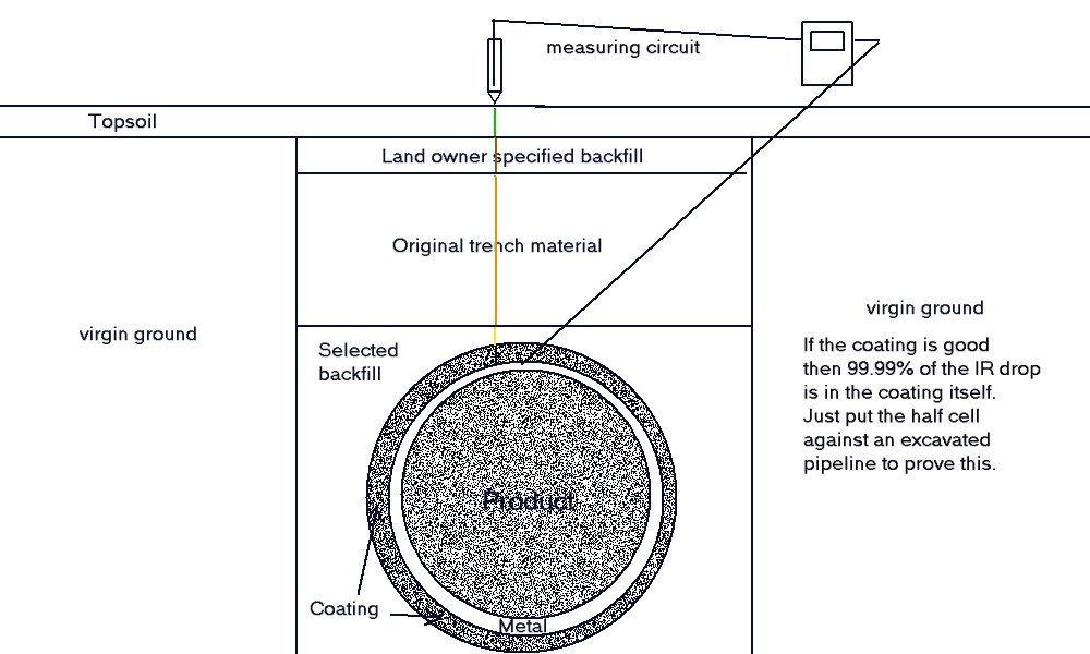
The resulting report describes the condition of the pipeline based on the electrical data gathered by an instrument that is programmed to log voltages between the pipeline metal and ground contact electrodes.
The measuring circuit is variable because of the resistance of the ground contact and the resistance of the trailing lead.
The potential of the ground itself is subject to electrical flux and the pipeline metal varies in potential due to conducted and induced charges.
The readings are analysed using graphs to assist in visualising all electrical influences and the effect they have on the corrosion status of the pipeline. We must remember that each voltage is simply the difference between two potentials and we are examining the difference between many VOLTAGES.
The baseline of the graph is NOT a fixed potential. This is because both the pipeline metal and the ground are subject to electrical flux.
The GPS position is logged at the same time as the measurements and events. This allows us to determine the exact position of the electrical information that we have gathered. This report relates these GPS positions to visible objects and in turn we have related these to Google Earth Images so that we can analyse the whole of the electrical circuit of which this pipeline is a single conductive path.
The instrument makes 50 or 60 thousand measurements per second and averages out samples determined by the software. The measurements flow through the meter as waves and it is the position at which the samples are taken on these waves that determin the voltage we see on the meter and which is recorded as our data.
The 'on' voltage is that when the wave is at it's highest level without counting an 'overrun' that appears as a spike. The 'off' voltage is made at an indeterminate part of the downward slope before the wave has levelled out at the bottom. It is very important to understand this because the 'off'reading is not a reliable voltage to assess the corrosion condition of the pipeline metal.
The 'polarised' potential can only be measured by switching off in a laboratory where the resistance of the electrolyte is between 1,500 and 50,000 Ohm/cm. It was tried in the field between the years of 1977 and 1985 and proved impossible to implement despite synchronisation of timers and the use of digital osciloscopes.
The graphs in this report represent the electrical measurements related to the time at which each voltage was measured and are related to the actual position of each measurement using GPS positioning that is synchronised with the logging system.