Two day training seminar
Period 6
What is Orac 2?
Orac 2 and Orac 2 mk 2 were stolen
I do not have a picture of Orac 2 as all my evidence was stolen as well. However, here is a description.
Orac2 was a model of a series of corrosion cells on a buried steel pipeline.
Orac2 could be taken just about anywhere in order to demonstrate a concept of pipeline corrosion and cathodic protection that may be contentious to conventional specialists.
What was Orac made of?
It was a briefcase, into which was built a sand tray which is designed to contain a variety of soil types separated only by thin netting.
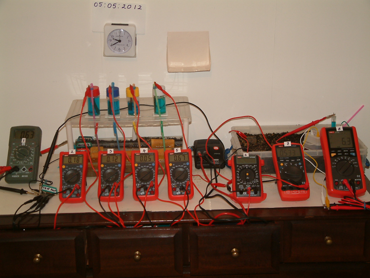
A row of 7 dry cell batteries, in holders, was arranged so that each battery could discharge direct current, through a steel electrode, to the sand tray. A common conductor, to the negative contact of each battery, completed the circuit.
Each battery could be by-passed, or controlled to discharge through a variable resistor causing a voltage drop, or a control causing a lower current output.
The current from each battery passes through a micro-ammeter before entering the electrode which discharges it to the soil samples in the sand tray.
The meter on the extreme right is an ammeter through which an impressed cathodic protection current can be passed.
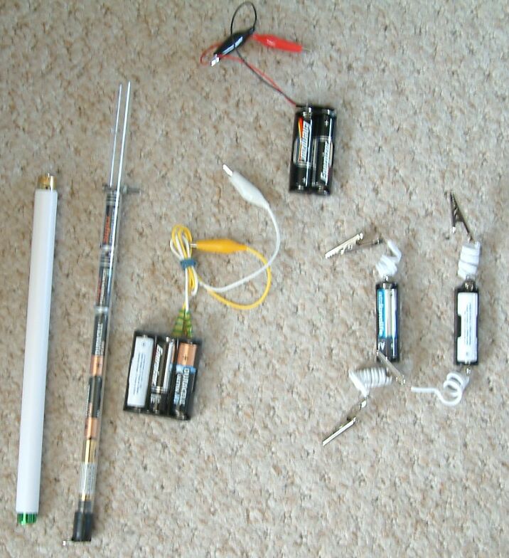
Orac 2 accessories
The pipeline is represented by seven pieces of steel pipe with a steel connecting tab raised at one end to allow connection to the ammeters.
The transformer/rectifier can be connected to the main conductor and to a suitable anode in the sand tray.
A magnesium electrode connected to a piece of wire can be used to cause interference to the readings.
A copper electrode connected to a piece of wire can be used to cause interference to the readings.
A water trough, separators and non-conductive rod can be used to demonstrate the effects of corrosion in water.
A standard copper/copper-sulphate electrode can be used to study conventional readings.
Two Alexander Cells can be used to examine this method of monitoring.
One isopotential Cell can be used to demonstrate the principles advocated by Dr Prinz.
The layout
Along the rear of the briefcase is a sand tray divided into a single trough that runs the full breadth and eight small compartments along the front. The dividers which separate the compartments, have each been fitted with a permeable plastic net to allow electrical contact between the contents.
The whole tray is filled with samples of soil or sand and is fitted with sliding a lid to keep the soil in position during transport.
The batteries are in holders which are stuck to the bottom of the briefcase in front of the sand tray. Each holder has two connections rising to the terminals of a variable resistor for each battery, fitted on the transparent plastic cover at the front.
Each of this row of variable resistors incorporates an on/off switch connected in such a way that when positioned in the 'off' mode, the current is diverted direct to the steel electrode connection. When each switch is turned 'on' the maximum resistance is engaged but the current from that particular battery is included in the whole circuit. As this resistor is rotated in a clockwise direction the resistance is lowered and the potential of the steel electrode is increased in relation to the electrolyte.
The controls in the rear row are designed to restrict the amount of current that can be drawn from each particular battery.
The connectors which protrude between the control panel and the sand tray, facilitate connection to the tabs on the steel pipe pieces.
A double black wire protruding from the front right hand corner is to be connected to the cathodic protection DC source.
At the extreme right rear of the clear plastic control panel a coiled red wire is fitted with a connection for attaching to a cathodic protection anode which can be placed anywhere in the sand tray.
Next to the cathodic protection anode connection is a black wire and connector which is part of the direct connections to the negative side of the battery system. This can be regarded as the pipeline test post, or facility to which the voltmeter negative is normally attached.
Setting up
The brief case should be placed on a flat level surface leaving a working space of about 200mm on the front three sides, to accommodate the accessories.
The brief case lid should be opened to its upright position and supported by extending the telescopic prop on the left hand side until it jams in the top let hand corner of the lid.
The lid of the sand tray should be removed by sliding towards the left had side, using the black plastic lip.
Check that all control knobs are set to the extreme anti-clockwise position and that the front row are 'clicked home' in this position to ensure that the batteries are switched out of the circuit.
Each of the batteries can be tested individually using the voltmeter. The negative probe of the meter is gripped in the test facility clip and the positive probe in the clip provided for the first pipe piece.
No reading should appear on the meter until the front control knob for this battery is clicked 'on' and from then it should be possible to obtain a variety of voltages using the two control knobs on this sector. The two control knobs should be returned to their extreme anti-clockwise position thus switching this battery out of the circuit again.
The positive probe of the voltmeter should then be moved to the clip provided for the next pipe piece and the procedure repeated. And so on....
Why is Orac 2?
Orac2 was build to demonstrate that corrosion cells on a buried pipeline can be regarded as dry cell batteries connected in parallel, and that an open circuit measurement will never be capable of determining the corrosion status of any one corrosion cell in the same way that open circuit measurements cannot determine the voltage of any single battery in this arrangement.
During the design of Orac2 it became apparent that we would have to allow the batteries to discharge into an electrolyte, to enable an open circuit measurement to be made, and what better way than through pieces of steel.
The electrolyte could be soil samples from typical pipeline backfill and therefore the arrangement would be close to reality.
It was then easy to see the advantages of providing the means to contain a variety of soils to show the effects of different electrolytes.
How does Orac 2 help?
When the steel pipe pieces are attached to their respective connecting leads and placed in the electrolyte we have an identical situation to 7 bare patches on a single section of buried pipeline.
With no battery power in circuit we can view the current strength and direction through each of the pieces of pipe, which results from their individual reaction with their specific electrolyte.
The batteries allow us to impose our own electrical pressures into the circuit and examine the effect on each element. We can therefore see the effect of a very powerful corrosion cell on several weaker cells, the effect of one anode and two, three or more cathodes or any permutation of seven anodes or cathodes.
We can impress cathodic protection on the pieces of pipe from any position in the sand tray and view the individual meters to see when each has stopped corroding. We can impress interference current from one of the inline batteries and view this being prevented by the cathodic protection.
We can use traditional measuring techniques to compare 'pipe-to-soil-potentials' with actual corrosion current flowing to and from each individual piece of pipe. We can observe the effect on these measurements of interference currents from the system and 'apparent' interference which gives reading errors where there is no effect on the pipe system.
What can we investigate using Orac 2?
We can examine the method of monitoring suggested by continental European specialists and the Alexander Cell, which in fact is simply a method of introducing another closed circuit corrosion cell at the chosen location.
Orac2 can be adjusted to give similar readings to those actually experienced in field work and can demonstrate the merits of various monitoring methods. It allows the student to put theory into practice and to form a concept of the reaction currents and the effects of cathodic protection.
If it is used over the period of a whole day, corrosion products can be observed on the pipe pieces to confirm that the current direction is indeed as indicated by the meters. (Faraday was right!).
The water trough can be situated in the sand tray allowing experiments to be carried out to demonstrate that the same rules apply in water conditions to those which apply in soil.
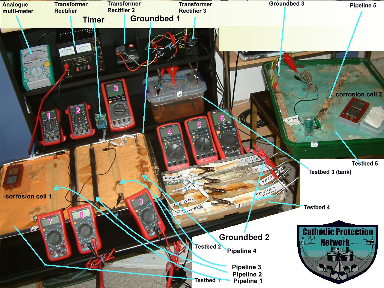
The bits and pieces
Meter 1
This is a typical digital multi-meter such as is available in any retail outlet. This actual meter has been in use for years alongside clients meters in cathodic protection monitoring field work. It measures similar values with similar accuracy to those used in industry, world-wide. It allows very little current to pass through the measuring circuit.
Meter 2
This is another digital meter similar to that used in the field for cathodic protection monitoring.
The data logger.
This is an opportunity to apply the data logger to record the voltages and dump them straight into a PC for reference and processing at a later date. This is the same data logger that has been used for field work in Nigeria.
What can Orac 2 demonstrate?
Orac2 can connect the seven pieces of steel without the inclusion of the batteries to simulate seven bare patches of steel on a length of buried pipeline. It can then be used to observe the behaviour of the current in the following experiments.
DIFFERENTIAL METAL CORROSION.
DIFFERENTIAL ELECTROLYTE CORROSION.
CATHODIC PROTECTION PREVENTING CORROSION CURRENT.
CONVENTIONAL PIPE-TO-SOIL POTENTIAL MEASUREMENTS.
CONVENTIONAL PIPE-TO-SOIL POTENTIAL MEASUREMENTS WITH IMPRESSED CATHODIC PROTECTION.
PIPE-TO-SOIL POTENTIAL MEASUREMENTS WITH INTERFERENCE BUT NO IMPRESSED CURRENT.
PIPE-TO-SOIL POTENTIAL MEASUREMENTS WITH INTERFERENCE AND IMPRESSED CURRENT.
THE IMPOSSIBILITY OF MEASURING THE VOLTAGE OF AN INDIVIDUAL DRY CELL IN THIS CONFIGURATION.
The present Orac2 (mk#n?)
.
The main pipeline
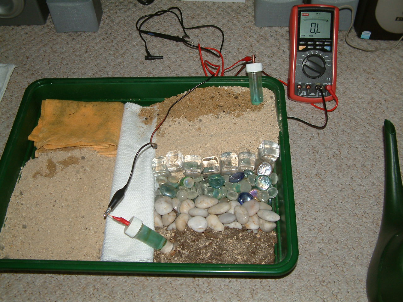
Visible corrosion pipeline
Different electrolyte pipelines

The bits and pieces
.
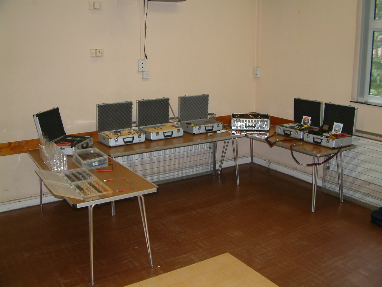
Orac 2 ultimate
Orac 2 ultimate functions
This part of the CPN laboratory in which I have observed and recorded the following corrosion reactions and effects of cathodic protection.
Differential metal corrosion.
Differential electrolyte corrosion .
Cathodic Protection preventing corrosion..
Conventional pipe-to-soil measurements.
Conventional pipe-to-soil measurements with impressed current on.
Conventional pipe-to-soil measurements with interference but no cathodic protection.
Pipe-to-soil measurements with interference and cathodic protection.
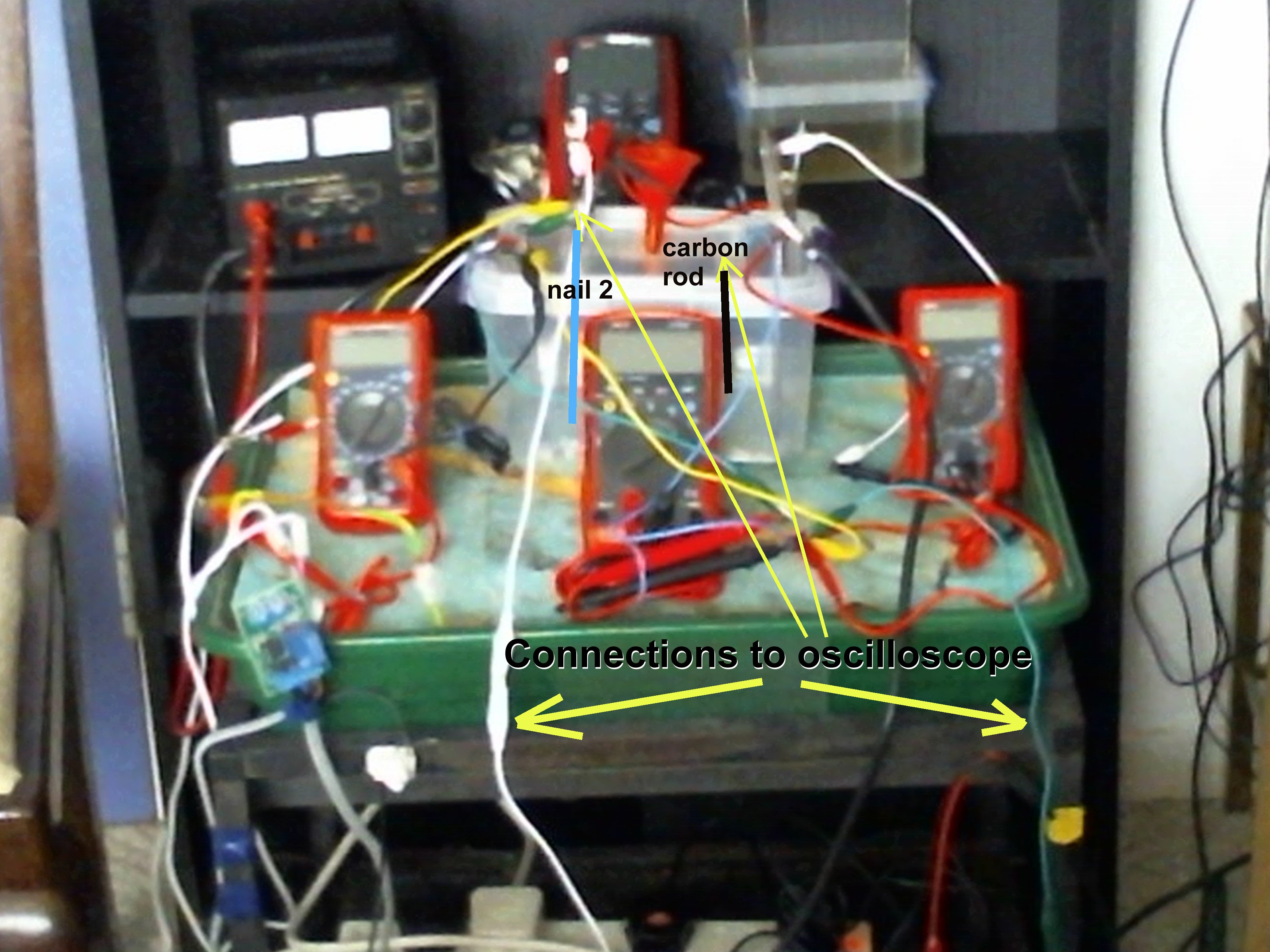
Pipe-to soil measurements with current interruption with oscilloscope.
Corrosion cell monitoring according to DIN50918
Monitoring using the isopotential cell.
The effects of 1, 2 and 3 transformer rectifiers at many settings and variable timers.
This is now possible

At no time have I found it possible to ascertain the corrosion status of a single location without the use of the Alexander Cell
It is not possible to computerise corrosion control without a criterion that can be regarded as zero.
Using the Alexander Cell as a trigger, it is possible to automate the control of pipeline networks using the communications that are now available for remote monitoring.