Two day training seminar
Period 2
My understanding of the history of CP
(other people may have a different view)
When CP was first introduced, it proved so cost effective that it became very widely used before its application in the field was fully understood. A short term measuring technique was required to monitor the performance, and the half-cell measurement was found to give a satisfactory indication.
Thermodynamic theory seemed to support this notion as the half-cell reaction was mentioned when describing reference electrodes in laboratories.
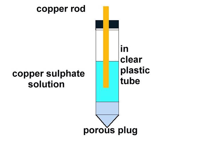
The electrode wrongly named the half-cell
My supervisors and advisors could not answer questions about the anomalies that occurred regularly on site.
Field technicians and engineers must have known, from the early years, that there was something wrong with the readings produced by the traditional pipe-to-soil potential measuring technique.
The first text book that I read on the subject was published in 1953, and some of the information it contained, simply did not work when applied in the field.
Pipe-to-soil potentials are the foundation of all CP work but the measuring techniques are still obscure and imprecise.
Many books and publications contain advice and information that do not yield the predicted results and this encouraged me to conduct my own field research and experiments which I have continued since 1972.
Physical demonstrations are necessary.
It is necessary to challenge the technical integrity of some existing axioms but this meets with opposition from many quarters of the establishment. It is therefore necessary to devise methods of demonstrating a series of facts which lead to irrefutable technical conclusions.
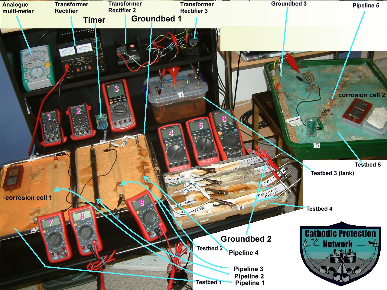
Many of these demonstrations are available at this seminar
These are all based on indisputable scientific theories and practices and those who have seen field demonstrations have confirmed that important issues are raised that affect all C.P. activities. Some 'specialists' are unable or reluctant to make field trips and continued opposition is met from some quarters within the establishment.
These issues have been taken to the very top academic authorities in the UK. and who are regarded as world leaders.
During this seminar, delegates should use these demonstration pieces as and when they wish to settle matters in their own minds. They are useful during discussions between delegates relating to scientific theory and formulae.
These demonstrations have been subject to up to 30 years of public scrutiny
The materials used in these demonstrations are all available at retail and the instruments are accurate and commonly used in our field work. Delegates should make their own experiments after this seminar to confirm to themselves that we are making correct changes to the perception of the way to apply and monitor cathodic protection and electronic control of corrosion.
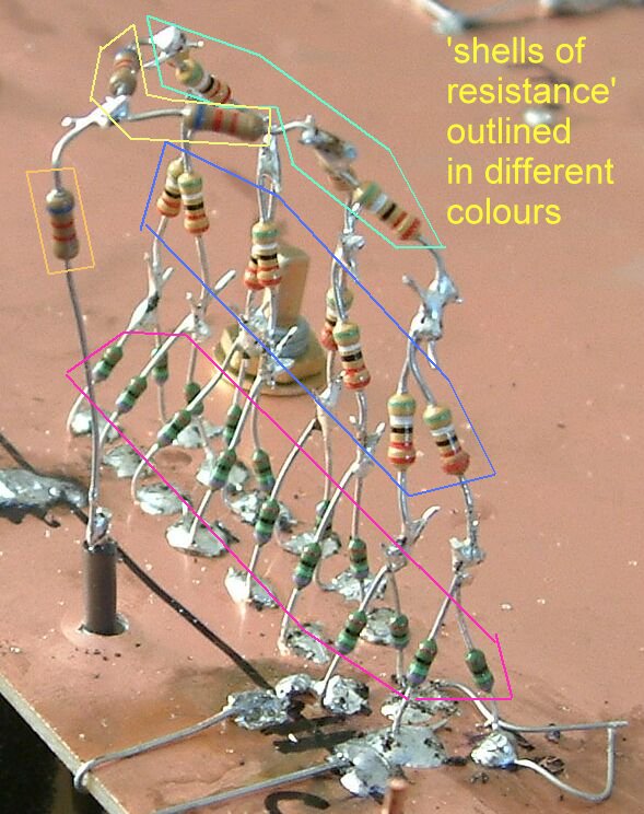
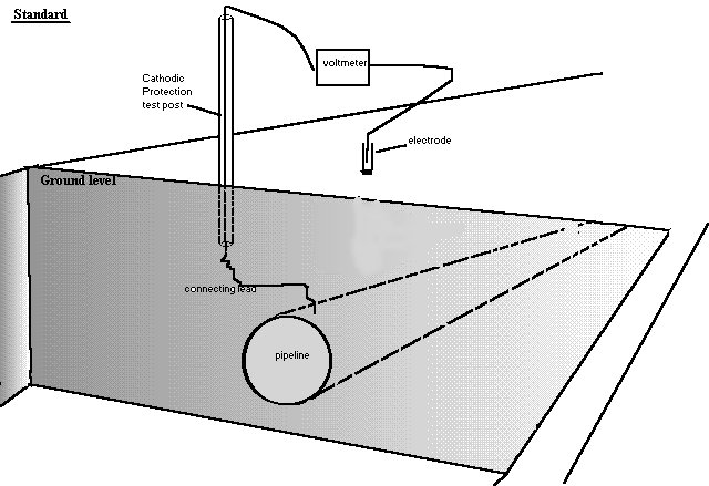
Pipe-to-soil voltage showing the 'shells of resistance'.
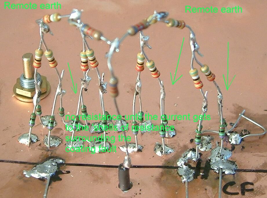
The concept of remote earth shown for real.
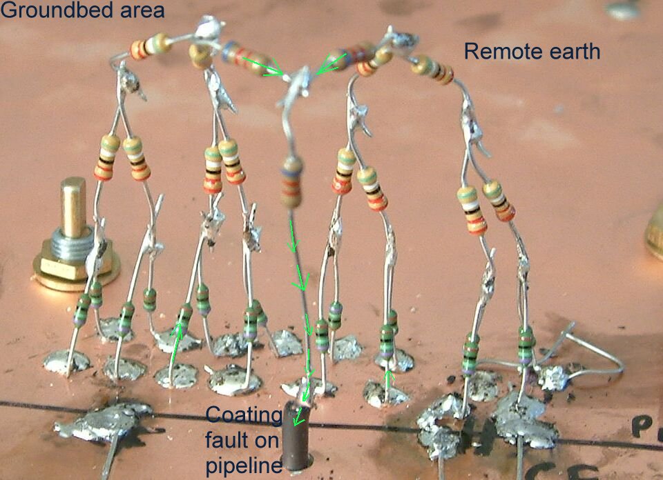
This structure allows reading exactly similar to those take as an excavation progresses at a coating fault.
All of these demonstrations have been computer modelled and compared with reality.
The problem and the solution.
The 'pipe-to-soil potential measurement' (voltage) has been described (in a paper by Peabody, published by NACE,) as an 'open circuit measurement', and this renders it impossible to eliminate errors which are not present in normal closed circuit electrical measurements.
The traditional technique for making the standard CP 'pipe-to-soil' became open to question when pipelines began to fail in spite of having been theoretically 'protected.
The word 'protected' has come to mean that the subject metal is connected to a cathodic protection system but not that corrosion has been controlled. At an insulation joint, one side is labelled 'protected' and the other 'unprotected'.
When a section of pipeline has reached the state of electrical equilibrium determined by one of three criteria it is recorded as having been protected, even though nobody has applied any test to see if corrosion has stopped.
Mobile displays can demonstrate the issue beyond dispute and have been presented to the Inst. Corr. Sc. and Tech. in London at a meeting which was attended by over 120 delegates, many of whom signed a document saying they were interested in further details.
This presentation in the 1980's resulted in the British Standards Institute reviewing the Code of Practice CP1021 and the Chairman of that committee gave me a copy of the paper supporting my views, that was presented at the Australasian Corrosion Conference by three European scientists who were firends of his. This paper had been ignored by NACE but I have evidence that the Institute of Corrosion Science and Technology (now ICorr) must have known about it.
My first paper was published in 1984 and I received response from specialists world-wide.
I visited corrosion specialists in the UK and found that they had agreed together to ignor my paper and suggestions.
I realised that the Alexander Cell showed that the established criteria for cathodic protection had nothing to do with the point at which corrosion is halted.
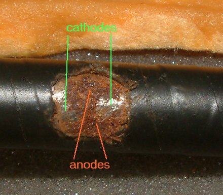
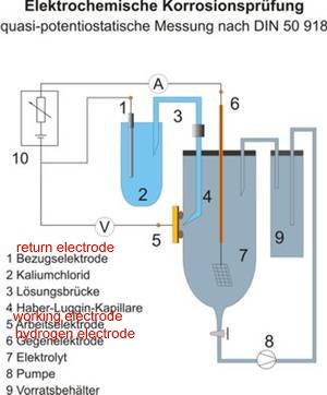
This is how corrosion should be measured.
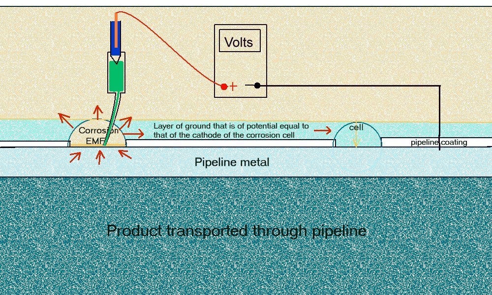
The probe is a lugin capillary to the ANODE of a corrosion cell.
A simplified drawing
DIN50918
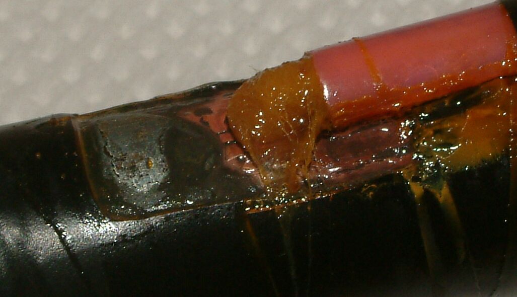
The arrangement of coupons that is the Alexander Cell
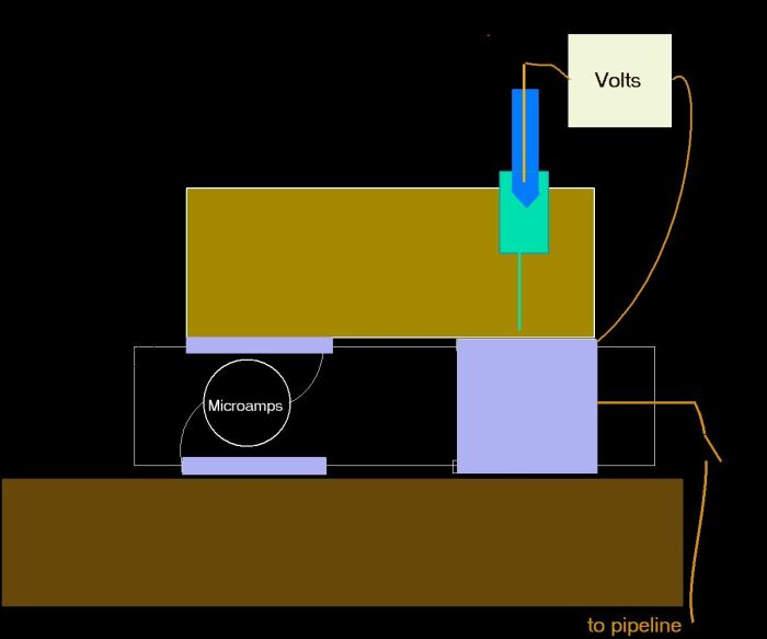
In this model wa can not only measure when corrosion has stopped but we can measure the reaction potential at the anode of the corrosion cell at this state of equilibrium.
We can use this as a criterion for cathodic protection in design, installation, commissioning and maintenance of our integrated corrosion control systems on networks of pipelines and facilities.
We can then correct the historical records of 'pipe-to-soil potential measurements' at each location of the Alexander Cell test.
We can then use this as a criterion that shows when corrosion actually stops.
This can be computer modelled and used as a trigger for automatic corrosion control when combined with one of the many remote monitoring systems that are available.
Because every pipeline cathodic protection system affects the electrical equilibrium of every other every other cathodic protection system we can use this data and the associated electronics to control corrosion on networks of pipelines.
This means that we have to work with the laws of nature and not with man made boundaries that nature itself ignors.
The solution to corrosion control is a co-operative effort between all parties who have an interest if maintaining their metalic assets.
This can only be done by computer.
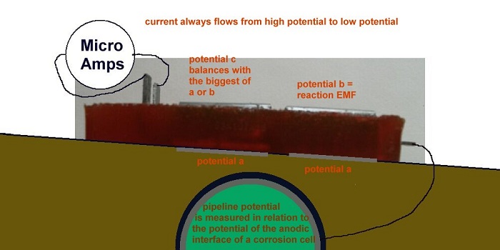
We can then use the electrical equilibrium in potentials and the cessation of corrosion current flow to indicate when we have stopped corrosion.
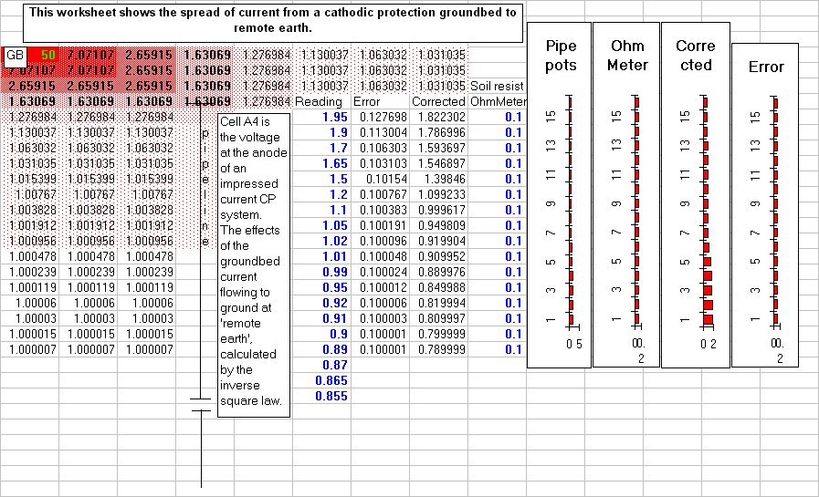
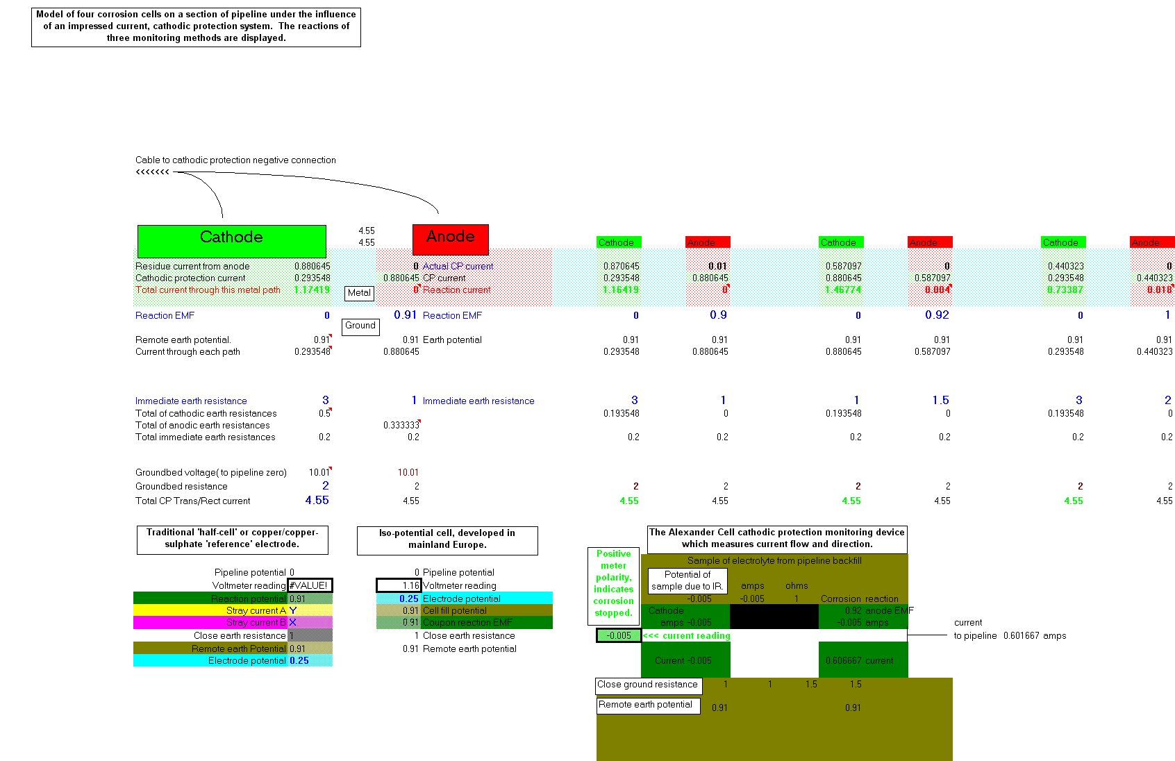
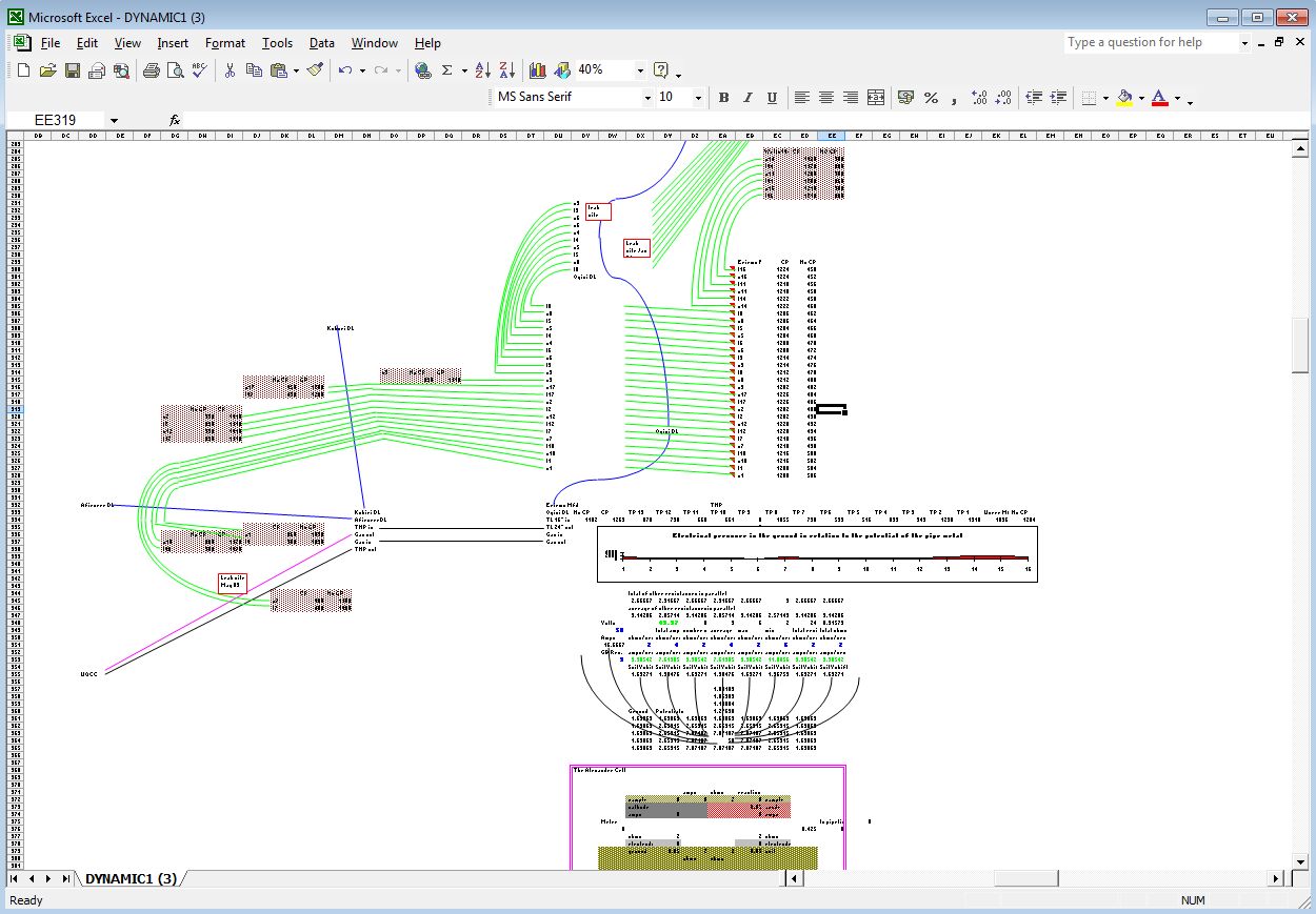
We need to measure energy transfer in a corrosion cell at each location that we subject to cathodic protection. (Coating faults), but as you can see from the above screenshot of the spread sheet, this cannot be determined by the use of the coppe/copper-sulphate electrode or by the use of the Isopotential cell. My bench experiments prove this to be so and so do all the field case studies that I have been involved over the past 30-40 years.
This seminar is not merely destructive criticism, as methods to overcome the problem, that has been identified, are included in the discourse.