
International Cathodic Protection Training Centre
and Research Facility
Functions of the facilities.
Training
DCVG Training Notes
Wrongly named Direct Current Voltage Gradient. It is is fact a survey that plots ground potentials. This was devised in Nigeria in 1975 to find pipework that had been buried during the Biafran War and no drawings were available as they had been bombed as well.
Bomu Manifold
A major manifold on the Trans-Niger Pipeline had been built over the damaged manifold to enable oil productiong to continue during the hostilities. Some of the old pipes were used and no insulating joints were built into the system.
In an attempt to get the cathodic protection running again a second transformer rectifier had been installed and when that failed to get 'protected' readings another groundbed has been constructed.
No-one knew where the CP current was going and there were no data loggers or digital multi-meters in that time. It was clear that the readings obtained by measuring between the pipeline metal and a copper/copper-sulphate electrode were not affected by changing the point of contact with the pipe and therefore the different readings were due to the ground in which the 'half-cell' was placed.
By moving the half cell, the ground potential could be plotted, but in some cases the old pipes jutting from the ground were used as connections and gave a different reading. This meant that they were not connected to the new pipes and to the CP systems.
Two half-cell survey
To overcome this confusion a remote half-cell was put in a fixed position and used as a reference against which to plot the voltages obtained by moving the roving half-cell on the other pole of the voltmeter.
The multi-meter at that time was a galvinometer and was more sensitive in the ammeter mode than in the voltmeter mode, so it was reasoned that by placing the half cell in a lower potential would cause more current to pass through the meter from the ground with the higher potential.
A contract was awarded to Mark Derefaka, a contractor, to plot all the directions of current tendencies and mark them with arrows showing the direction of flow. We then plotted the ground potentials in relation to each other.
By switching each of the transformer rectifiers in turn, it was then possible to plot the resulting changes in ground potential and trace the exact positions of buried pipes.
We found corrosion on the pipes as predicted by the current flow and found some of the burried pipes protected by stay current coming onto their surface from the soil.
The success of this method of survey led to the use of two half-cells throughout Shell BP Development Corporation in Nigeria and resulted in visits from Shell International engineers from The Hague to see the procedure.
I used the two half cell procedure extensively during the development of CIPS by The Gas Council in the UK in the early 1980's. The Gas Council was sold into private hands and became the Gas corporation and later broken up into smaller companies, British Gas and Transco.
Using the two half cell method to find an ordinary coating fault.
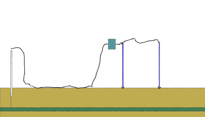
Two half-cells as walking sticks
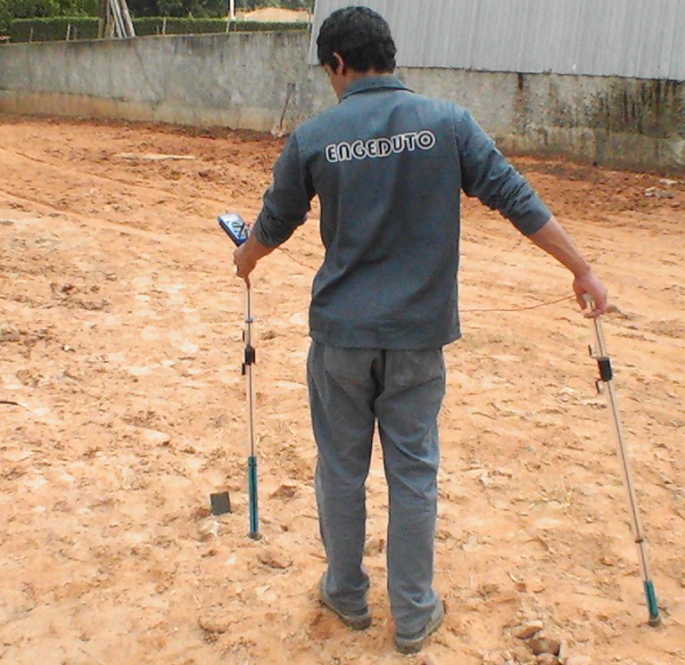
In this procedure (Now known as DCVG) each pole of the voltmeter is connected to a half-cell at the end of an arrangement that allows the user to touch them to the ground as he walks. The half-cells shown above are the simplest form of this but the same can be achieved by inserting standard half-cells into tubes.
The meter shows the voltage between the two locations on the ground at the points of contact. It is important to be aware that this is a voltage measurement and NOT a POTENTIAL MEASUREMENT!!. A potential measurement can only be made in laboratory conditions in closed circuit.
Two different ground potentials
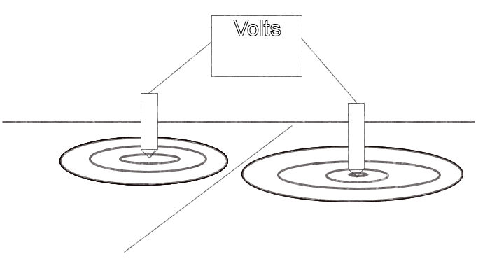
This is a voltage and is the difference between two potentials. We do not know the value of either potential but simply the difference between the two.
It is therefore clear that the polarity of the voltage changes as each half cell is stepped forward in the manner of walking. Therefore a gradient in the voltage is shown as a 'saw tooth' if these readings are plotted on a recording voltmeter or data logger.
Typical 'saw-tooth'plot.
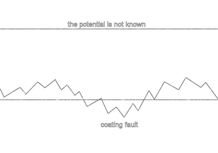
When using a digital voltmeter the user will see the negative sign at alternative steps towards a coating fault as the value of the reading increases.
When over the coating fault it can be seen that the polarity will change and a saw tooth upwards trend will be seen towards the ground that is not close to the coating fault. This is towards 'remote earth' in that it is not affected by the potential of the pipe metal.
This is the most important and basic concept in cathodic protection monitoring. It is clear that we are measuring the difference in the potential of the ground in which one half cell is placed by compartison to the potential of the ground in which the other half cell is placed.
The half-cell cannot be regarded as a 'reference potential' in these circumstances as there is a voltage reading between the two. A voltage is a potential DIFFERENCE and as each half-cell is of identical construction and has the same EMF there should not be any difference if regarded as reference electrodes. Indeed it is the requirement of calibration that there is no difference between two 'half-cells'!
CIPS Training
In the CIPS survey we attach one pole of the voltmeter to a CP test post and the other to a 'roving half-cell'. In fact, this is two half-cells connected to one pole of the voltmeter in order that one is always in contact with the ground.
It can be seen that there is always a voltage between the poles of the meter and the reading does not drop to zero or change polarity as it does during the DCVG type of survey.
We are therefore able to plot a more consistant voltage and detect more features that affect the ground potential.
However, the pipeline potential is not constant and we have to set up recording voltmeters or data loggers to measure the flucuations in the pipeline potential itself.
All the data that we gather must be related to a fixed reference potential so that a computer can calculate the actual potential at each interface between the pipe metal and the backfill/electrolyte.
We use CPN Procedure 2 for this purpose.
At the training centre we are able to simulate most of the errors that have been called 'the IR Drop in the soil'. This means a potential difference between the contact point of the half-cell and the backfill closest to the bare metal of the pipeline at a coating fault.
The first of these is
Depression caused by dry cell battery.
The DCVG survey showed that we can trace a coating fault on a pipeline because of the depression that the cathodic protection current causes in the potentials on the surface of the ground.
It must be remembered that the surface is two dimensional but the ground below is three dimensional. We should visualise the effects of the reading coming from a hemisphere of the ground. This is very important as electricians tend to deal with linear paths and must adjust their thinking to adapt to 'open circuit measurements'.
The coating fault causes a hemospherical 'shell of potentials' as the current from the transformer/rectifier passes from remote earth towards the bare metal.
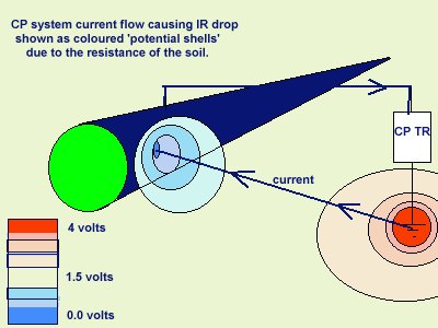
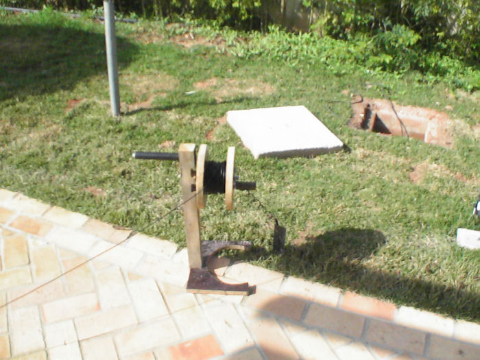
Remote earth is disturbed by other currents and electrical influences and we can demonstrate one of these by placing a dry cell battery in the ground with it's terminals in contact with the earth.
In order to exagerate the effect we have arranged a series of dry cell batteries in a plastic tube. This increases the voltage between the two terminals that contact the earth.
Tube of batteries
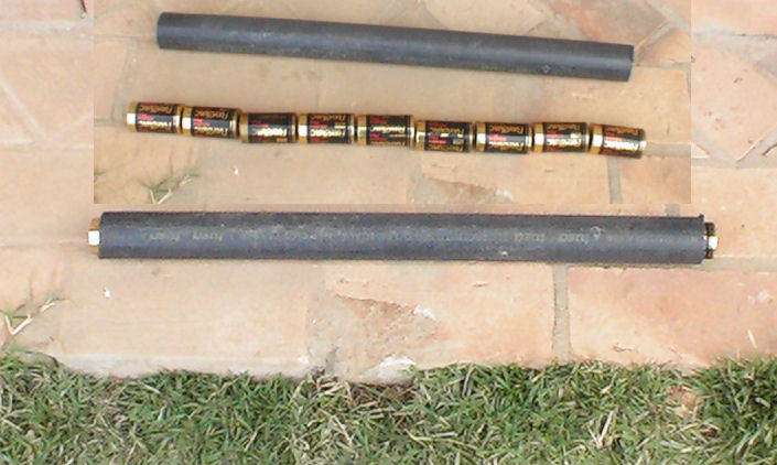
By stepping the 'roving half-cell' around the tube of batteries we are able to plot the potential gradients in the ground.
These potential gradients are superimposed on other potentials, caused by currents from other sources.
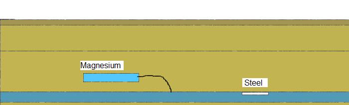
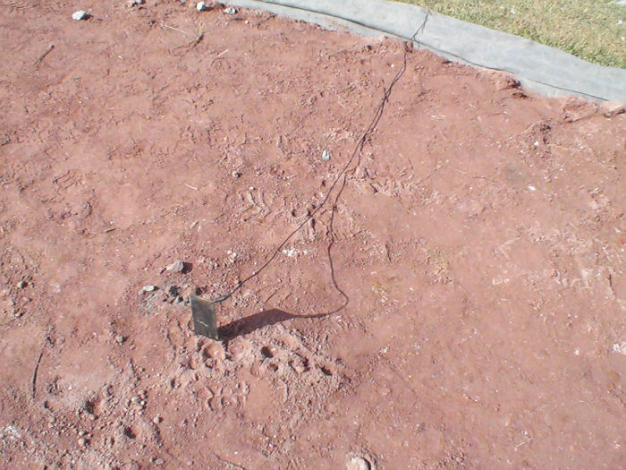
Depression caused by bi-metalic coupling.
When two metals are connected together in an electrolyte the less noble metal disolves and releases energy. The more noble metal is protected from corrosion by the energy passing into it from the electrolyte. This is the principle of sacrificial cathodic protection.
We are able to cause this effect by driving a steel coupon into the ground near to a copper coupon and connecting the two together by a jumper lead with a crocodile clip on each end.
Steel and copper driven into the earth having no effect on the ground potentials
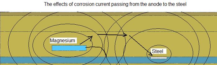
Connecting the steel to the copper allows the current to flow and equilibrium is reached as long as the current flows.
Wetting the ground into which the coupons are driven makes better electrical contact as the water disolves more of the salts in the ground and the solution makes better contact with the metal.
We can then plot the 'isopotential map' of the ground and see how far the corrosion current of the steel travels to complete the circuit.
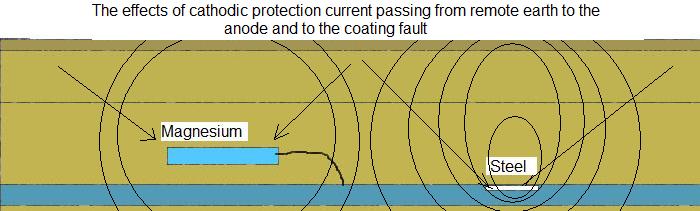
We can then superimpose this potential profile over the coating fault to observe the effects.
Peak masking coating fault.
If we place the steel over the coating fault and the copper remote then we can see that the depressed potential of the ground over the coating fault is masked by the increased potential of the same ground due to the corrosion current given off by the steel.
this is a section through the earth showing the potential 'shells' of the copper, steel and pipeline due to corrosion current and CP current.
Remember that this will not affect the corrosion on the pipeline unless the bimetalic coupling is close enough to the coating fault that it's corrosion current finds a less resistant path through the pipeline than it would otherwise find through the ground.
Peak caused by Sacrificial anode.
A sacrificial anode is simply one half of a bi-metalic coupling... the pipeline being the other half.
The easiest way to detect the rise in ground potential caused by the corrosion of the sacrificial anode is to use a remote half cell as a reference and step the other half-cell over the area until the peak in the ground potentials is identified.
It is also simple to apply the principles of DCVG and step two half cells over the ground where you think the anode might be.
If you find a peak, then the anode is causing an increase in the ground potential and is helping to protect the pipe but if this turns into a depression when the impressed current is switched
on then it is clear that the impressed current is protecting the anode.
Our TR at the training centre has the capability of protecting both sacrificial anodes and all the other junk we chose to bury.
Masking caused by bare metal connected to negative terminal of the TR.
By adjusting the TR to give a theoretically 'protected' reading at a coating fault we can then show the effect of placing a row of steel coupons on the TR side.
When we connect these to the negative terminal of the TR they will mask the coating fault by depriving it access to the charges from the groundbed. The same effect is commonly found from one side of the pipeline to the other during DCVG and CIPS surveys if the coating is bad.
It is for this reason that the anodic and cathodic nature of a coating fault cannot be determined by DCVG surveys. Any result you want can be achieved by simply swapping the half-cells round and altering the polarity of the meter.
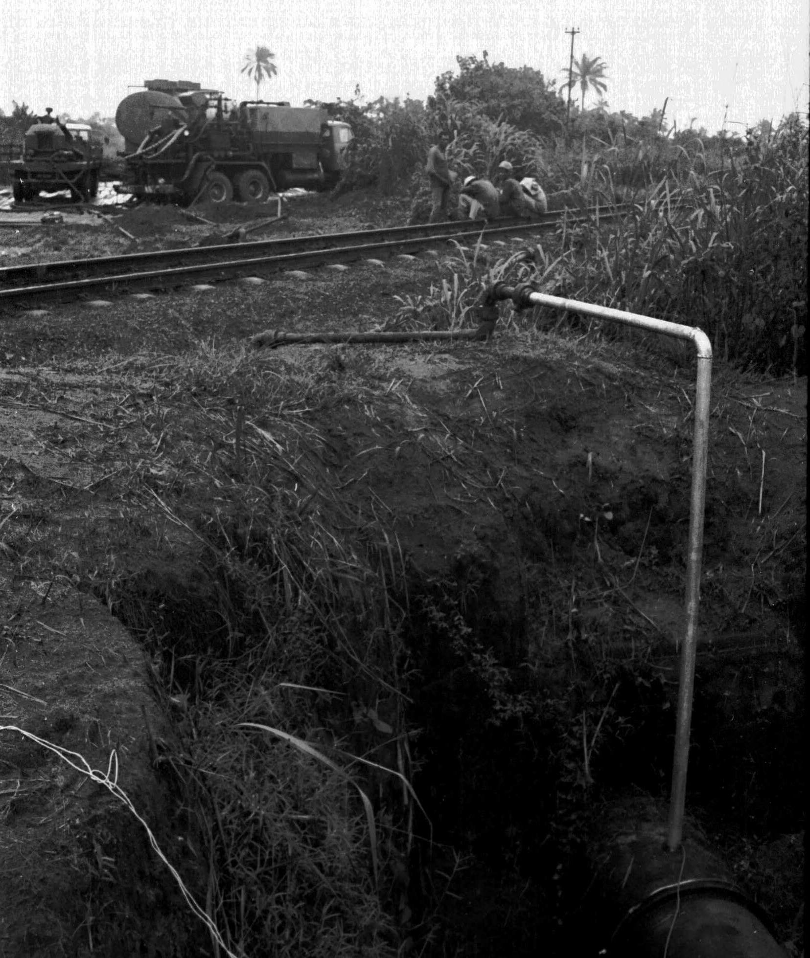
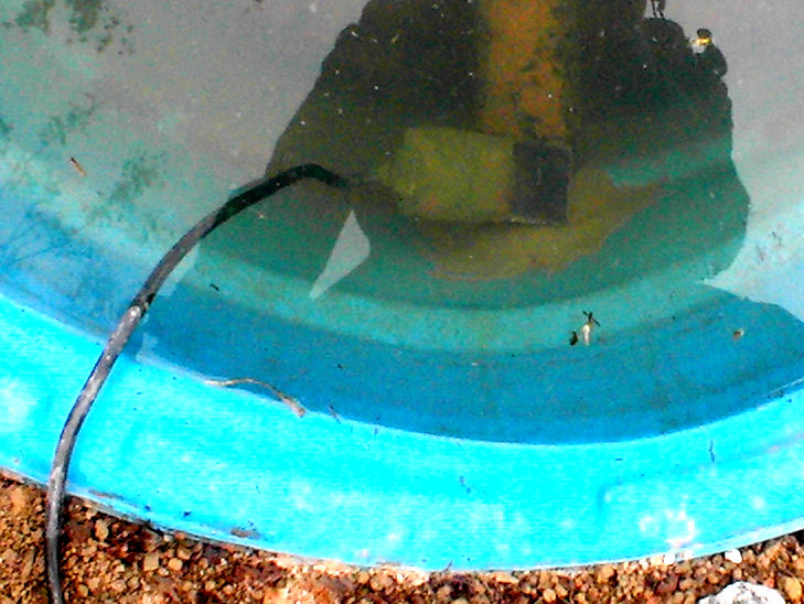
Masking caused by shorted sleeve.
This is easily demonstrated at the training centre at the test post by shorting the sleeve while taking pipe to soil measurements.
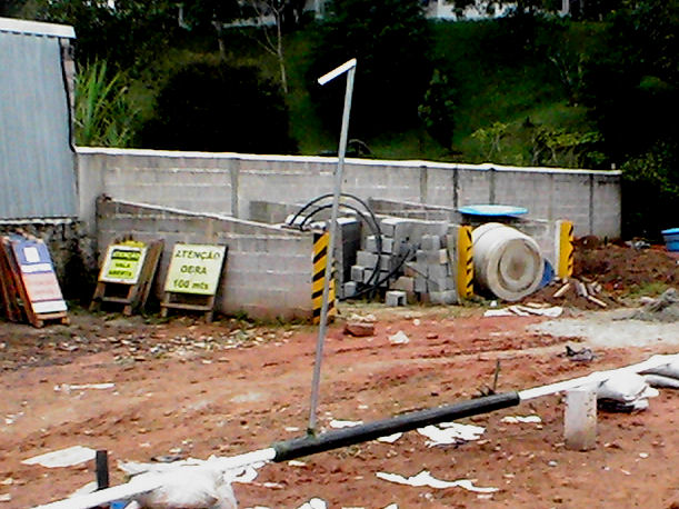
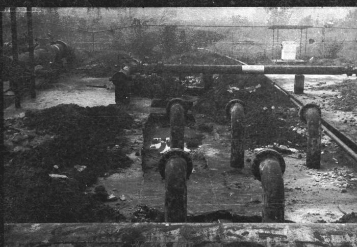
If the sleeve is shorted to the pipeline it will have the effect of a massive coating fault. Sleeved crossings are often constructed by 'thrust bore' techniques in which the sleeve is pushed through the ground with hyraulic rams while a miner digs away the spoil. Neither inside or outside of the sleeve are coated and the pipeline is later pushed through the sleeve with insulating spacers to electrically seperate the metal of the pipe from that of the sleeve. In the process of construction the spacers often get snagged and buckled and their metal components bridge the anulus.
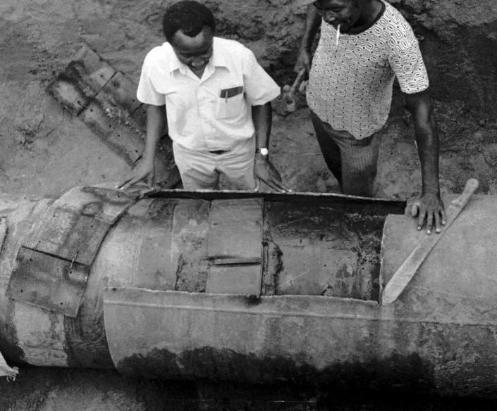
The picture shows an example of a short circuit that prevented cathodic protection current from reaching areas of a pipeline beyond the sleeved crossing. Another shorted sleeve was between the next transformer and this one so the area between the crossings was shielded from any cthodic protection.
The situation was made worse by the fact that the anulus between the pipe and sleeve in one case was flooded with brackish water and therefore corrosion could progress inside the sleeve. It passed under a main railway and no repair could be made in the event of a leak.
By manipulating the pipeline configuration we were able to remove the short circuit and then pump the anulus full of epoxy compound to insulate it and secure it's relative position.
The effect of shielding is to lower the potential of the ground and therefore the apparent higher potential of the pipeline is exagerated.
When the cathodic protection current is switched off, the ground potential increases at the same time as the pipeline potential.
This does not necessarily mean that there is insufficient protection at the anodic interface of a corrosion cell in this locality.
This can be used as an example that the immediate off reading does not necessarily remove the 'IR drop in the soil' as proposed in the CIPS survey.
Peak caused by conductive path from the GB.
A long lead is connected to a coupon driven into the ground near the groundbed
and another over the pipeline.
The charges are conducted to cause an increase in the potential of the ground into which they are discharged. At 1345 hrs on 21st July 2009 a coupon was set as above
River crossing insulated.
The water crossing is a plastic bowl through which the pipe passes without a coating fault.
The first experiment is to demonstrate that the well coated pipeline has no influence on the potential of the water through which it passes and that the water might not be influenced by the surrounding ground, dependant on the conductivity of the ground that has trapped the water.
A pipe to soil voltage reading is taken with the half-cell in the water and then with the half-cell in the ground immediately outside.
A two half cell measurement is taken with one half-cell in the water and the other immediately outside.
A half cell is placed remote as a reference and the other stepped across the area of the water and two steps in the water.
River crossing shorted to GB.
A long line connector from a coupon by the groundbed is clipped to a coupon in the water.
This conducts the potential from the groundbed earth to the water which then attains an equal potential.
The experiments in the last section are repeated noting that the readings reflect the raising of the potential of the water. They cannot have affected the potential of the pipeline itself as it is well insulated from the water.
River crossing shorted locally.
The river crossing can be made to resemble the potential balance of a normal river by 'short circuiting' it with the surrounding soil. All it requires is a coupon in the water and a coupon in the soil near to the water.
The potential of the soil then equalises with the potential of the water.
This is the normal situation as a river passes through areas of differennt ground potential and this is why the location of each CP groundbed should be studied on a map of the whole pipeline.
A River crossing with simulated coating fault.
For this purpose we have made up coupons with specific areas of bare steel and can connect any one of these to the pipeline at the last test post.
By placing the coupon in the water we can simulate a coating fault of that size on the pipeline metal.
The amount of current flowing between the coupon and the pipe steel is negligible so there will be no voltage drop of any significance.
Remote earth switching.
When CIPS was devised by Mike Foskett and Bob Greenwood of British Gas in the early 1980's they thought that the cathodic protection current followed the path of the pipeline and that readings should be taken immediately over the pipeline.
During the first moments of the survey it became obvious to those of us in the field that where the coating is good, then it does not make any difference to the voltage if the half-cell is immediately over the pipeline or in the next field 200 meters away.
This is because the coating effectively makes the position of the half-cell in 'remote earth' because of it's high electrical resistance. The cathodic protection current only flows where it can return to the negative terminal of the transformer rectifier, and therefore if there is no coating fault the current cannot flow onto the pipeline. This in turn means that there is no voltage drop in the ground above the pipeline as all of the drop is contained in the coating itself.
When a transformer rectifier is switching and a voltage is taken between the pipe and remote earth, the effects can be measured many miles from the pipeline.
It is sometimes possible that this can be measured as 'interference' through a continuous conductor such as another pipeline or a railway track.
The understanding of the principles of remote earth conductance is essential to a cathodic protection engineer.
Remote bi-metalic coupling.
A bi-metalic coupling placed in remote earth will retain it's equilibrium with that ground when the ground is switching in relation to the pipeline. We can demonstrate this at the training centre by switching the TR and taking two half-cell measurements of the ground potentials around a remote coupling.
If the remote half cell is on the groundbed side and the coupling is arranged so that it receives a certain amount of the CP interference then this can be seen in the voltages.
Remote AC ground potential fluctuations.
The ground carries AC currents that can affect cathodic protection readings and might affect corrosion on the pipeline. The theory is that corrosion products have the effect of diodes and tend to rectify AC currents into DC which can pass onto the pipe. This raises the pipe metal potential and causes the pipe metal to be at a higher potential than the soil in other locations.
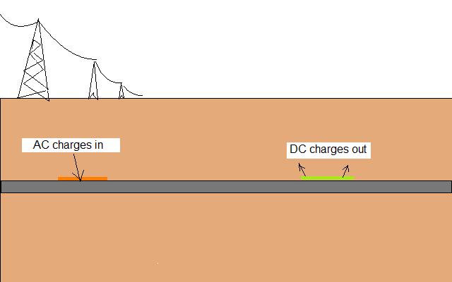
The rectifed current passing into the soil accelerates corrosion by increasing the charges available at the anodic interface. It could also cause the metal at the cathodic interface to turn anodic.
Remote DC ground potential fluctuations.
The most quoted cause of DC potential ground fluctuations is the railway where the current returns via the ground.
The normal way of addressing this problem is for a diode to be fitted between the pipeline and the railway track at the location that the current is most likely to leave the pipeline.
Each case where this remedy is used must be subject to an 'electrical examination' by drawing the circuit and defining the equilibrium of the local system.
We can simulate such systems at the training centre.
World energy suppliers are now using DC transmission at very high voltages (1 mega-volt and above) over long distances. In Europe there are serious studies that might lead to solar energy from the Sahara Desert being transported to central Europe using DC through the earth and the positive being through a liquid helium pipeline.... an almost perfect conductor.
There is concern amongst some corrosion engineers that this could affect pipeline cathodic protection systems in the path of such currents.
Close earth switching.
Where the earth close to the pipeline is switching, then this may affect the corrosion status of the pipeline if there is a coating fault in the vicinity.
Indeed a coating fault is normally the cause of the earth potential changes.
We can demonstrate other causes using sacrificial anodes and batteries.
Close earth fluctuations. DC generator....welding....holiday detector.
Close earth fluctuations can be caused by a generator being wrongly earthed.
Off potential... slow depolarisation.
Due to the way we have constructed the training centre pipelines, we can vary the time it takes for the system to depolarise and show that switching the CP off can produce a variety of results during the CIPS survey depending on the timeing of the 'on' and 'off' measurements as well as the exact time that the voltage is logged.
This is very important as all Petrobras criteria are based on the theory that we can measure a 'polarised' value in the 'off' mode. This is not the case as it is only possible to measure such a value in a laboratory where the pH of the quantified.
Without being able to measure this value the present critera are worthless and there is no acceptable way to guage if the cathodic protection is stopping corrosion.
CIPS surveys have only got any value if they are corrected by CPN procedures and the criterion is fixed using the Alexander Cell at each location.
Students will be shown spread sheet models on a computer that prove that this is the case using electrical calculations that are required to be known by most school children.
Depression during on and off modes.
We will show a depression in the ground potential being caused by the copper coupon of a bi-metalic coupling set over the pipeline.
This depression is due to the corrosion current from the corroding magnesium passing from the soil into the copper. This depletes the charges in the ground surrounding the copper.
Similar effects are experienced in the field where is is not always possible to determin the source or exact circuit of the current.
Peak during on and off modes.
As with the copper causing a depression in the ground potential, the magnesium of the coupling will cause a peak in the potential and this will be apparent in the CIPS readings.
Each of these features is either adding to or subtracting from the value of the total ground potential.
Peak in 'on' mode and not in 'off'. extension from GB.
A peak in voltages that appears in the 'on' mode and not in the 'off' mode will be associated with the CP system by not with the pipeline itself.
This is because the pipeline will take longer to depolarise than the period it is switched off whereas something influenced by the positive terminal of the TR might not depolarise at all.... it might have no capacitance to hold a charge.
Depression in 'on' mode and not in 'off'.
This occurs when there is some form of conductance from the negative terminal of the transformer rectifier that will not polarise.
This might be a metal object accidentally in contact with one of the connecting wires or telemetry or instrumentation that links a manifold pipework and its supports to the TR negative. Copper or cupra/bronze earthing systems do not polarise.
Ordinary coating fault -depression in 'on' and 'off'.
An ordinary coating fault
Alexander Cell
The Alexander Cell is a corrosion cell arranged in such a way that the corrosion current can be measured in closed circuit. It can then be attached to the pipeline and the corrosion current can still be measured in closed circuit.
This cannot be achieved with a natural corrosion cell as it's current must pass only through the earth that is continuous and open to other currents and electrical influences.
Attempts have been made to measure corrosion currents in open circuit but even if this could be achieved the effects of cathodic protection must be superimposed over both the anode and cathode of the cell.
It has been suggested that driving a steel spike in the ground achieves the same result as the Alexander Cell.
This is not the same as we do not know if the steel spike is corroding independantly or because of it's connection to the pipe. In either case there will be both anodes and cathodes on the steel spike in the same way as on the pipeline and cathodic protection current will always pass onto the spike and the pipeline via the cathodic interfaces.
We have no way of telling if the anodes have stopped corroding.

The Alexander Cell is first prepared by polishing both base electrodes to cause an equal reaction to the earth on which they are placed.
The anode of the two top electrodes is also polished to make it less noble than the cathode of the top two electrodes.
The cathode of the top two electrodes is wiped clean of loose electrolyte but not cleaned as we want this metal to be passive to the new sample of electrolyte.
A sample of electrolyte is taken from the backfill of the pipeline as close as possible to the pipe itself and the Alexander Cell is placed in the ground from which the sample is taken.
This ensures that the pH of the reaction electrolyte is the same as that to which the pipeline coating faults are subjected and satisfies the requirements of the Pourbaix Diagramns.
The sample of electrolyte is placed in an innert porous bag and placed across the top of the cell.
The electrolyte reacts with the polished anode and the sample becomes charged by the EMF of the reaction.
The cathode is passive and conductive so the charges enter the other electrode on the top of the cell.
A low resistance ammeter measures the current that then passes to the electrode in contact with the earth below the cell.
The earth becomes charged to a higher level than the other base electrode and the current enters to complete the corrosion current circuit in the anode on top of the cell.
This is an exact replica of a corrosion cell on the pipeline but has a low resistance ammeter in circuit tha can measure the corrosion current.
Corroding
We therefore have a corrosion cell in the same location as the pipeline and we know the strenght and direction of the current. We know which is the anode and which is the cathode. 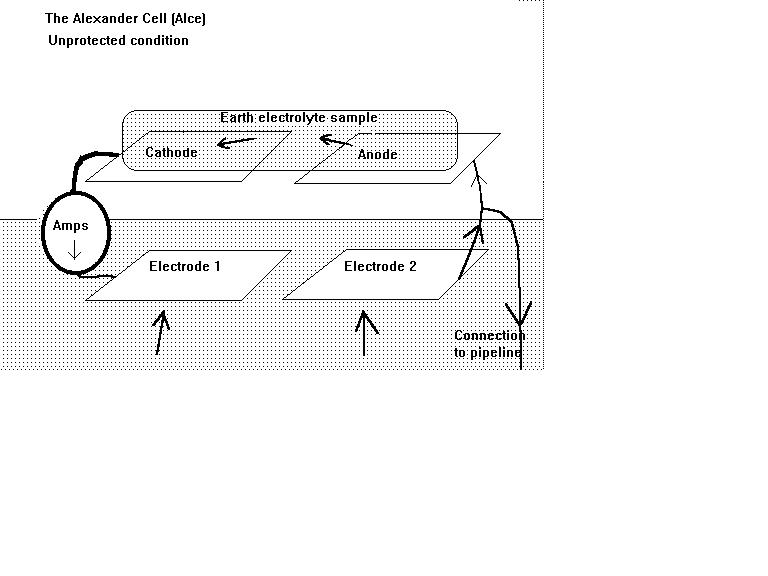
The cathodic protection current can enter the pipeline through either the cathode or the anode of a natural corrosion cell but it only stops corrosion if it enters the anode.
We know this because current will flow from a higher potential to a lower potential.
When the potential of the ground at the anodic interface is higher than the anode metal then corrosion must stop as the EMF has not sufficient energy to discharge current. ( Gibbs Free Energy...relative to the Nerst Equations)
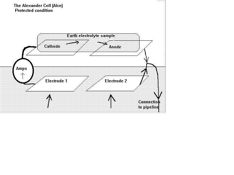
Protected
This condition is reached when the current stops passing through the ammeter as the cell is connected to the pipeline.
The exact pipe-to-soil voltage at which this status is reached must be recorded together with the exact position of the half-cell.
This voltage will be corrected back to a common reference electrode for the whole network of pipelines and the computer will then be able to calculate the balance required to stop corrosion at this location.
Not protected.
If the ammeter does not reverse polarity then there is insufficient charge in the ground to stop corrosion. The cathodic protection current density is not enough.
The cathodic protection TR should be adjusted so that there is no corrosion current flowing and this can be seen in real time.
Isopotential Cell
The Isopotential cell was invented by a group of scientists from Europe in the early 1980's following the publication of their paper at the Australasian Corrosion Conference in Tasmania.
Demonstration and experiments to show intended use.